Support » Pololu 3pi Robot User’s Guide » 5. How Your 3pi Works »
5.d. Digital inputs and sensors
The microcontroller at the heart of the 3pi, an Atmel AVR mega168 or mega328, has a number of pins which can be configured as digital inputs: they are read by your program as a 1 or a 0 depending on whether the voltage is high (above about 3 V) or low (below about 1.5 V). Here is the circuit for one of the pushbutton inputs:
 |
Normally, the pull-up resistor R (20-50 k) brings the voltage on the input pin to 5 V, so it reads as a 1, but pressing the button connects the input to ground (0 V) through a 1 k resistor, which is much lower than the value of R. This brings the input voltage very close to 0 V, so the pin reads as a 0. Without the pull-up resistor, the input would be “floating” when the button is not pressed, and the value read could be affected by residual voltage on the line, interference from nearby electrical signals, or even distant lightning. Don’t leave an input floating unless you have a good reason. Since the pull-up resistors are important, they are included within the AVR – the resistor R in the picture represents this internal pull-up, not a discrete part on the 3pi circuit board.
A more complicated use for the digital inputs is in the reflectance sensors. Here is the circuit for the 3pi’s leftmost reflectance sensor, which is connected to pin PC0:
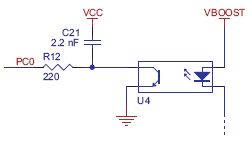 |
The sensing element of the reflectance sensor is the phototransistor shown in the left half of U4, which is connected in series with capacitor C21. A separate connection leads through resistor R12 to pin PC0. This circuit takes advantage of the fact the digital inputs of the AVR can be reconfigured as digital outputs on the fly. A digital output presents a voltage of 5 V or 0 V, depending on whether it is set to a 1 or a 0 by your program. The way it works is that the pin is set to an output and driven high (5 V) to charge the output node. The pin is then set to an input, and the voltage falls as current flows through the phototransistor. Here is an oscilloscope trace showing the voltage on the capacitor (yellow) dropping as current flows through the phototransistor, and the resulting digital input value of pin PC0 (blue):
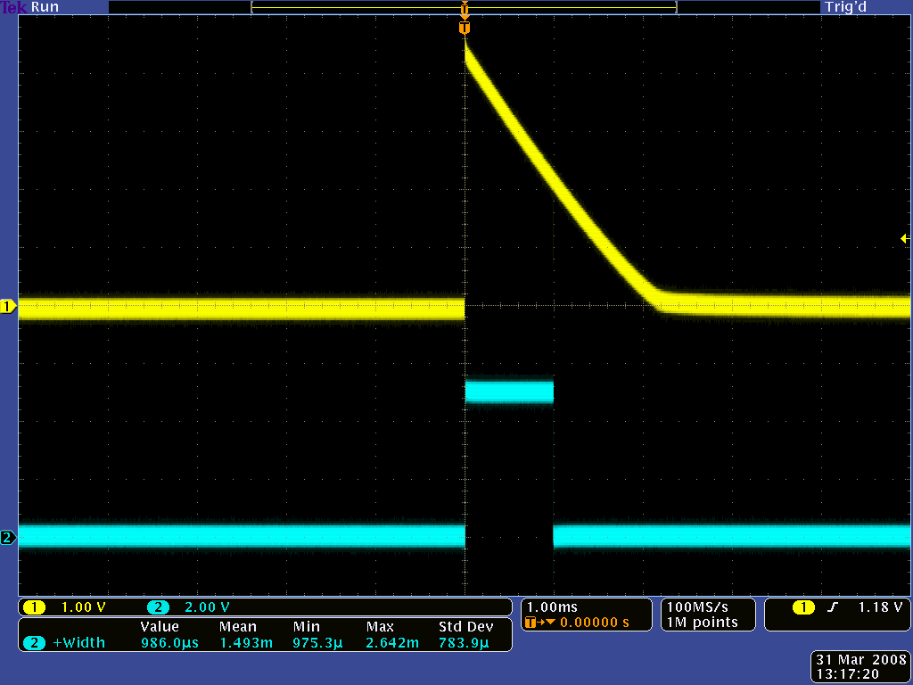 |
The rate of current flow through the phototransistor depends on the light level, so that when the robot is over a bright white surface, the value returns to 0 much more quickly than when it is over a black surface. The trace shown above was taken when the sensor was on the edge between a black surface and a white one – this is what it looks like on pure white:
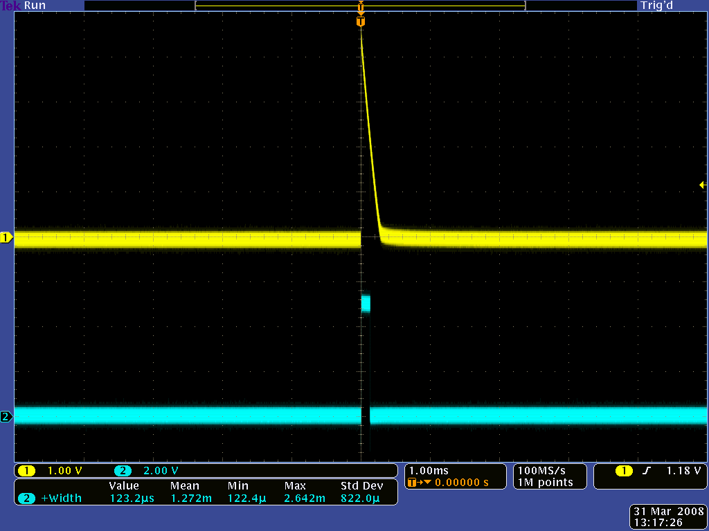 |
The length of time that the digital input stays at 1 is very short when over white, and very long when over black. The function read_line_sensors() in the Pololu AVR Library switches the port as described above and returns the time for each of the five sensors. Here is a simplified version of the code that reads the sensors:
time = 0;
last_time = TCNT2;
while (time < _maxValue)
{
	// Keep track of the total time.
	// This implicity casts the difference to unsigned char, so
	// we don't add negative values.
	unsigned char delta_time = TCNT2 - last_time;
	time += delta_time;
	last_time += delta_time;

	// continue immediately if there is no change
	if (PINC == last_c)
		continue;

	// save the last observed values
	last_c = PINC;

	// figure out which pins changed
	for (i = 0; i < _numSensors; i++)
	{
		if (sensor_values[i] == 0 && !(*_register[i] & _bitmask[i]))
			sensor_values[i] = time;
	}
}
This piece of code is found in the file src\PololuQTRSensors\PololuQTRSensors.cpp. The code makes use of timer TCNT2, which is a special register in the AVR that we have configured to count up continuously, incrementing every 0.4 μs. Basically, the code waits until one of the sensors changes value, counting up the elapsed time in the variable time. (It is important to use a separate variable for the elapsed time since the timer TCNT2 periodically overflows, dropping back to zero.) Upon detecting a transition from a 1 to a 0 on one of the sensors (by measuring a change in the input port PINC), the code determines which sensor changed and records the time in the array sensor_values[i]. After the time limit _maxValue is reached (this is set to 2000 by default on the 3pi, corresponding to 800 μs), the loop ends, and the time values are returned.


Home | Forum | Blog | Support | Ordering Information | Lists | Distributors | BIG Order Form | About | Contact
© 2001–2026 Pololu Corporation
