Support » Pololu 3pi Robot User’s Guide » 5. How Your 3pi Works »
5.c. Motors and Gearboxes
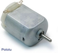 |
A typical small brushed DC motor, with no gearbox. |
|---|
A motor is a machine that converts electrical energy to motion. There are many different kinds of motors, but the most important for low-cost robotics is the brushed DC motor, which is the type used on the 3pi. A brushed DC motor typically has permanent magnets on the outside and several electromagnetic coils mounted on the motor shaft (armature). The “brushes” are sliding pieces of metal that switch the power from one coil to the next as the shaft turns so that magnetic attraction between the coil and the magnets continuously pulls the motor in the same direction.
The primary values that describe a running motor are its speed, measured in rpm, and its torque, measured in kg·cm or oz·in (pronounced “ounce-inches”). The units for torque show the dependence on both force and distance; for example, a motor that produces 6 oz·in of torque can product a force of 6 oz. with a 1-inch lever arm, 3 oz. with a 2-inch lever, and so on. Multiplying the torque and speed (measured at the same time) give us the power delivered by a motor. We see, therefore, that a motor with twice the speed and half the torque as another has the same power output.
Every motor has a maximum speed (when no force is applied) and a maximum torque (when the motor is completely stopped). We call these the free-running speed and the stall torque. Naturally, a motor uses the least current when no force is applied to it, and the current drawn from the batteries goes up until it stalls, so the free-running current and stall current are also important parameters characterizing the motor. The stall current is usually much higher than the free-running current, as shown in the graph below:
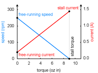 |
Motor operation: current and speed vs. torque. |
|---|
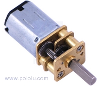 |
The 30:1 gearmotor used on the 3pi. |
|---|
The free-running speed of a small DC motor is usually many thousands of rotations per minute (rpm), much higher than the speed we want the wheels of a robot to turn. A gearbox is a system of gears that converts the high-speed, low-torque output of the motor into a lower-speed, higher-torque output that is a much better suited for driving a robot. The gear ratio used on the 3pi is 30:1, which means that for every 30 turns of the motor shaft, the output shaft turns once. This reduces the speed by a factor of 30, and (ideally) increases the torque by a factor of 30. The resulting parameters of the 3pi motors are summarized in this table:
| Gear ratio: | 30:1 |
|---|---|
| Free-running speed: | 700 rpm |
| Free-running current: | 60 mA |
| Stall torque: | 6 oz·in |
| Stall current: | 540 mA |
The two wheels of the 3pi each have a radius of 0.67 in, which means that the maximum force it can produce with two motors when driving forward is 2×6/0.67 = 18 oz. The 3pi weighs about 7 oz with batteries, so the motors are strong enough to lift the 3pi up a vertical slope or accelerate it at 2 g (twice the acceleration of gravity). The actual performance is limited by the friction of the tires: on a steep enough slope, the wheels will slip before they stall – in practice, this happens when the slope is around 30-40°.
Driving a motor with speed and direction control
One nice thing about a DC motor is that you can change the direction of rotation by switching the polarity of the applied voltage. If you have a loose battery and motor, you can see this for yourself by making connections one way and then turning the battery around to make the motor spin in reverse. Of course, you don’t want to take the batteries out of your 3pi and reverse them every time it needs to back up – instead, a special arrangement of four switches, called an H-bridge, allows the motor to spin either backwards or forwards. Here is a diagram that shows how the H-bridge works:
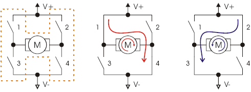 |
If switches 1 and 4 are closed (the center picture), current flows through the motor from left to right, and the motor spins forward. Closing switches 2 and 3 causes the current to reverse direction and the motor to spin backward. An H-bridge can be constructed with mechanical switches, but most robots, including the 3pi, use transistors to switch the current electronically. The H-bridges for both motors on the 3pi are all built into a single motor driver chip, the TB6612FNG, and output ports of the main microcontroller operate the switches through this chip. Here is a table showing how output ports PD5 and PD6 on the microcontroller control the transistors of motor M1:
| PD5 | PD6 | 1 | 2 | 3 | 4 | M1 |
|---|---|---|---|---|---|---|
| 0 | 0 | off | off | off | off | off (coast) |
| 0 | 1 | off | on | on | off | forward |
| 1 | 0 | on | off | off | on | reverse |
| 1 | 1 | off | off | on | on | off (brake) |
Motor M2 is controlled through the same logic by ports PD3 and PB3:
| PD3 | PB3 | 1 | 2 | 3 | 4 | M2 |
|---|---|---|---|---|---|---|
| 0 | 0 | off | off | off | off | off (coast) |
| 0 | 1 | off | on | on | off | forward |
| 1 | 0 | on | off | off | on | reverse |
| 1 | 1 | off | off | on | on | off (brake) |
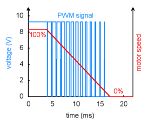 |
PWM speed control, showing gradual deceleration. |
|---|
Speed control is achieved by rapidly switching the motor between two states in the table. Suppose we keep PD6 high (at 5 V, also called a logical “1”) and have PD5 alternate quickly between low (0 V or “0”) and high. The motor driver will switch between the “forward” and “brake” states, causing M1 to turn forward at a reduced speed. For example, if PD6 is high two thirds of the time (a 67% duty cycle), then M1 will turn at approximately 67% of its full speed. Since the motor voltage is a series of pulses of varying width, this method of speed control is called pulse-width modulation (PWM). An example series of PWM pulses is shown in the graph at right: as the size of the pulses decreases from 100% duty cycle down to 0%, the motor speed decreases from full speed down to a stop.
In the 3pi, speed control is accomplished using special PWM outputs of the main microcontroller that are linked to the internal timers Timer0 and Timer2. This means that you can set the PWM duty cycle of the two motors once, and the hardware will continue to produce the PWM signal, in the background, without any further attention.
The set_motors() function in the Pololu AVR Library (see Section 6 for more information) lets you set the duty cycle, and it uses 8-bit precision: a value of 255 corresponds to 100% duty cycle. For example, to get 67% on M1 and 33% on M2, you would call
set_motors(171,84);
To get a slowly decreasing PWM sequence like the one shown in the graph, you would need to write a loop that gradually decreases the motor speed over time.
Turning with a differential drive
The 3pi has an independent motor and wheel on each side, which enables a method of locomotion called differential drive. It is also known as a “tank drive” since this is how a tank drives. It is completely unlike the steering system of automobile, which uses a single drive motor and steerable front wheels. Turning with a differential drive is accomplished by running the two motors at different speeds. In the previous set_motors() example, the left wheel will spin faster than the right, driving the robot forward and to the right. The difference in speeds determines how sharp the turn will be, and spinning in place can be accomplished by running one motor forward and one backward. Spinning is an especially effective maneuver for a round robot, and you won’t have to worry about parallel parking!
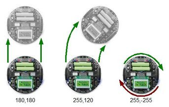 |
The 3pi demonstrating the effects of various motor settings. |
|---|


Home | Forum | Blog | Support | Ordering Information | Wish Lists | Distributors | BIG Order Form | About | Contact
© 2001–2024 Pololu Corporation
