Support » Pololu QTR Reflectance Sensor Application Note »
1. Introduction
The Pololu QTR reflectance sensors can be used to sense how much infrared light is reflected from a nearby surface. The QTR sensors are intended to be used as line sensors in line-following, maze-solving, and sumo robots, but they can be used as general purpose proximity or reflectance sensors. They are available in two output types:
- RC-type sensors can be read by timing a signal on a digital I/O line.
- A-type sensors output an analog voltage.
This application note explains how both types of sensors work and what their output signals look like.
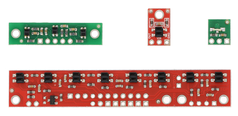
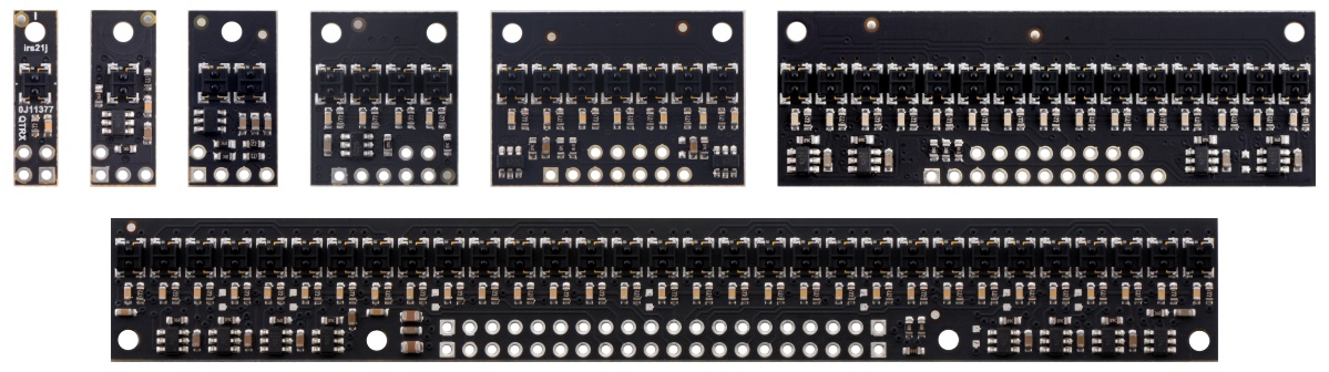
First- and second-generation QTR sensors
Our older (first-generation) QTR sensors, introduced prior to August 2018, mostly have red and green PCBs. These sensor boards do not have integrated LED drivers, so their emitter brightness depends on the supply voltage.
 |
Our newer (second-generation) QTR and QTRX sensors have black PCBs and feature integrated LED drivers that provide brightness control independent of the supply voltage and optional dimming to any of 32 possible brightness settings. They are available in a wide range of sizes and in High-Density (4 mm pitch) and Medium-Density (8 mm pitch) versions; HD arrays with five or more sensors additionally provide separate control of the odd-numbered and even-numbered LEDs for greater versatility.
 |
The information about sensor output types in Section 2 and Section 3 applies to both the first- and second-generation sensor boards. Section 4 explains details specific to the second-generation QTR/QTRX sensors.
Related products


Home | Forum | Blog | Support | Ordering Information | Lists | Distributors | BIG Order Form | About | Contact
© 2001–2026 Pololu Corporation
