Support » Pololu QTR Reflectance Sensor Application Note »
3. A-type sensor output (analog voltages)
Each A-type reflectance sensor phototransistor output is connected to a pull-up resistor as shown below to form a voltage divider that produces an analog voltage output that ranges between 0 V and the supplied voltage (which is typically 5 V). With a strong reflectance, such as when the sensor is over a white surface, its output voltage will tend towards 0 V; with very weak reflectance, such as when the sensor is over a black surface, its output voltage will tend towards the supplied voltage. Different QTR sensor products have different component values, and exact schematics for each QTR sensor can be found on its product page.
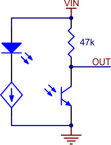 |
Schematic diagram of an individual QTR sensor channel on an A-type board. This applies only to the newer QTRs with dimmable emitters. |
|---|
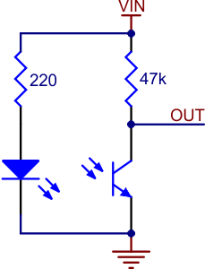 |
QTR-1A reflectance sensor schematic diagram. |
|---|
To demonstrate what the A-type sensor output looks like as it passes from a reflective surface to a non-reflective surface and back again, we set up a motor to spin a white paper circle with a piece of black electrical tape on it as shown below.
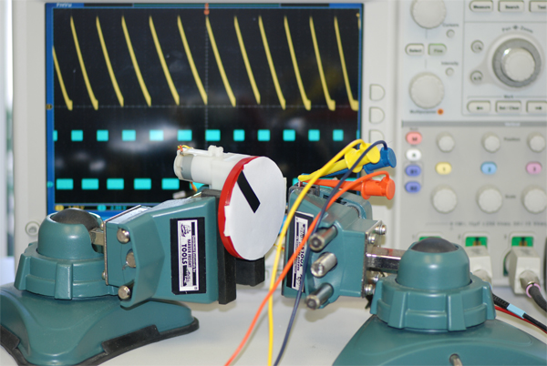 |
Experimental setup for QTR-1A and QTR-1RC oscilloscope outputs. |
|---|
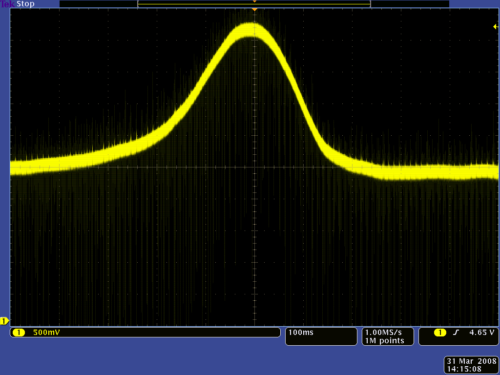
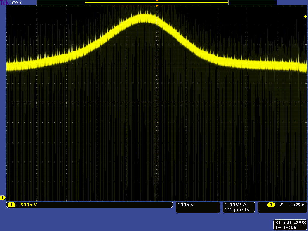
The following three oscilloscope screen captures show the output of the QTR-1A reflectance sensor during the period where the black line passes by the sensor. The oscilloscope is set to 500 mV per division. The only difference between the three captures is the distance from the sensor to the disk: ~1/8″ in the first capture, ~1/4″ in the second capture, and ~3/8″ in the third capture.
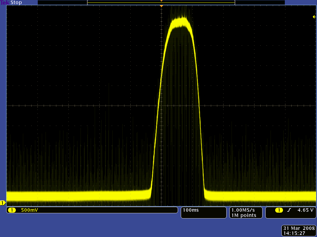 |
QTR-1A output 1/8" away from a spinning white disk with a black line on it. |
|---|
 |
QTR-1A output 1/4" away from a spinning white disk with a black line on it. |
|---|
 |
QTR-1A output 3/8" away from a spinning white disk with a black line on it. |
|---|
As the distance between the sensor and the surface increases, the overall reflectance decreases and the total range of the sensor output decreases. At a distance of 1/8″, the difference between the white surface and the black surface is around 4.5 V. At a distance of 3/8″, the difference between the white surface and the black surface has decreased to around 1.2 V, which makes distinguishing between the two surfaces much harder and much more prone to error caused by noise or changes in lighting conditions.
Note that in these captures you can clearly see the effect of the motor’s noise on the output signal. This underscores the importance of filtering your sensor output if it will be in a potentially noisy environment, either by using a low-pass filter circuit or by averaging several sensor readings together.
Related products


Home | Forum | Blog | Support | Ordering Information | Wish Lists | Distributors | BIG Order Form | About | Contact
© 2001–2024 Pololu Corporation
