Support » Pololu QTR Reflectance Sensor Application Note »
4. Second-generation QTR/QTRX sensor array details
Sensor options
Two different sensor options are available on our second-generation reflectance sensor arrays, denoted by “QTR” or “QTRX” in the product name. The QTR versions feature lower-cost sensor modules without lenses while the QTRX versions feature higher-performance sensor modules with lenses, which allow similar performance at a much lower IR LED current. You can see the two different sensor styles in the pictures below of the 4-channel modules:
|
|
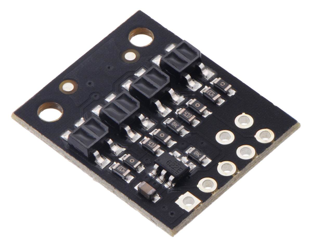
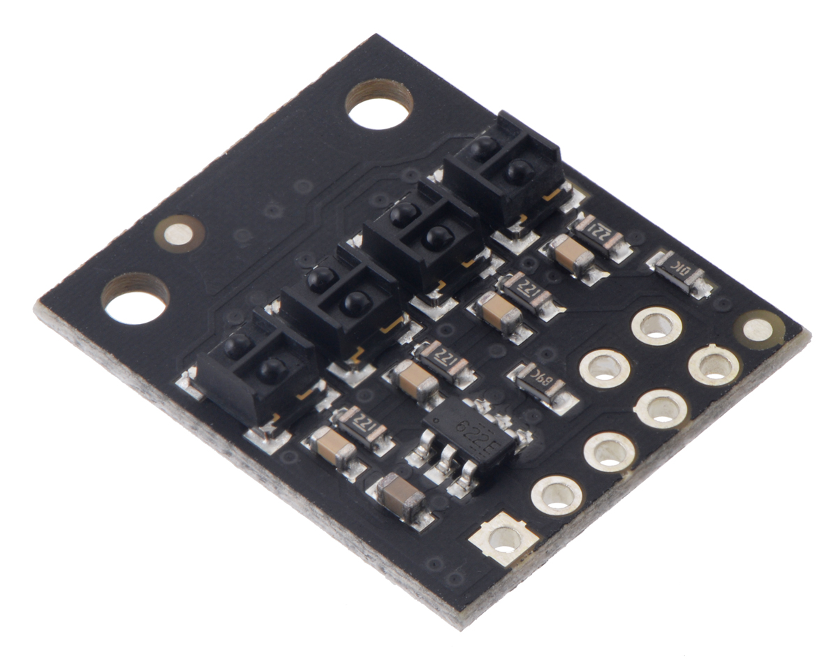
A disadvantage of the QTRX sensor modules is that they leak light out the sides and can interfere with each other when they are closely spaced (unless barriers are added between the sensors). Consequently, the maximum emitter current on QTRX arrays is set low enough to limit the interference while optimizing their useful range. This is not an issue with a single sensor, so we offer high-brightness QTRXL versions of the 1-channel boards in addition to the normal-brightness QTRX versions, but it is still important to consider interference when using multiple 1-channel boards.
This video (taken with an old camera that does not have as much IR filtering as most newer cameras) shows the IR light leakage around the side of the QTRX sensor module:
Emitter control
The second-generation reflectance sensor arrays maintain a constant current through their IR emitters, keeping the emitters’ brightness constant, independent of the supply voltage (2.9 V to 5.5 V). The emitters can be controlled with the board’s CTRL pins, and the details of the control depends on the array size and density:
- Units with five or more sensors in a high-density (HD) arrangement have two emitter control pins: CTRL ODD and CTRL EVEN. By default, these are connected together with a 1 kΩ resistor and pulled up, turning on all the emitters by default and allowing them to be controlled with a signal on either pin, but the CTRL ODD and CTRL EVEN pins can be driven separately for independent control of the odd-numbered and even-numbered emitters.
- Units with three or more sensors in a medium-density (MD) arrangement also have two emitter control pins since these are made by only populating every other sensor on an HD board, but only the CTRL ODD pin will have an effect on these versions (it is not possible to independently control alternate emitters).
- Units with four or fewer sensors have a single CTRL pin that controls all of the emitters.
Driving a CTRL pin low for at least 1 ms turns off the associated emitter LEDs, while driving it high (or allowing the board to pull it high) turns on the emitters with the board’s default (full) LED current, which is 30 mA for QTR and QTRXL boards and 3.5 mA for QTRX boards. (The emitter LEDs are generally driven in pairs, with the two emitters in each pair connected in series, so the total board current is not the LED current times the number of LEDs as you might otherwise expect; it is usually closer to half that.)
|
|
For more advanced use, the CTRL pin can be pulsed low to cycle the associated emitters through 32 dimming levels. To send a pulse, you should drive the CTRL pin low for at least 0.5 μs (but no more than 300 μs), then high for at least 0.5 μs; (it should remain high after the last pulse). Each pulse causes the driver to advance to the next dimming level, wrapping around to 100% after the lowest-current level. Each dimming level corresponds to a 3.33% reduction in current, except for the last three levels, which represent a 1.67% reduction, as shown in the table below. Note that turning the LEDs off with a >1 ms pulse and then back on resets them to full current.
| Dimming level (pulses) |
Emitter current (%) |
Dimming level (pulses) |
Emitter current (%) |
|
|---|---|---|---|---|
| 0 | 100.00% | 16 | 46.67% | |
| 1 | 96.67% | 17 | 43.33% | |
| 2 | 93.33% | 18 | 40.00% | |
| 3 | 90.00% | 19 | 36.67% | |
| 4 | 86.67% | 20 | 33.33% | |
| 5 | 83.33% | 21 | 30.00% | |
| 6 | 80.00% | 22 | 26.67% | |
| 7 | 76.67% | 23 | 23.33% | |
| 8 | 73.33% | 24 | 20.00% | |
| 9 | 70.00% | 25 | 16.67% | |
| 10 | 66.67% | 26 | 13.33% | |
| 11 | 63.33% | 27 | 10.00% | |
| 12 | 60.00% | 28 | 6.67% | |
| 13 | 56.67% | 29 | 5.00% | |
| 14 | 53.33% | 30 | 3.33% | |
| 15 | 50.00% | 31 | 1.67% |
For example, to reduce the emitter current to 50%, you would apply 15 low pulses to the CTRL pin and then keep it high after the last pulse.
Related products


Home | Forum | Blog | Support | Ordering Information | Wish Lists | Distributors | BIG Order Form | About | Contact
© 2001–2024 Pololu Corporation
