

This is a merged information page for Item #2970.
View normal product page.
Pololu item #:
2970
Brand:
Pololu
Status:
End-of-Life Rationing

This is a breakout board for ON Semiconductor’s AMIS-30543 microstepping bipolar stepper motor driver, which features SPI-adjustable current limiting, 11 step modes (from full-step through 1/128-step), back-EMF feedback that can be used for stall detection or optional closed-loop control, and over-current and over-temperature protection. The board operates from 6 V to 30 V and can deliver up to approximately 1.8 A per phase without a heat sink or forced air flow (it is rated for 3 A per coil with sufficient additional cooling).
 Compare all products in Stepper Motor Drivers.
|
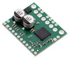
AMIS-30543 stepper motor driver carrier. |
|---|
 |
AMIS-30543 stepper motor driver carrier with included hardware. |
|---|
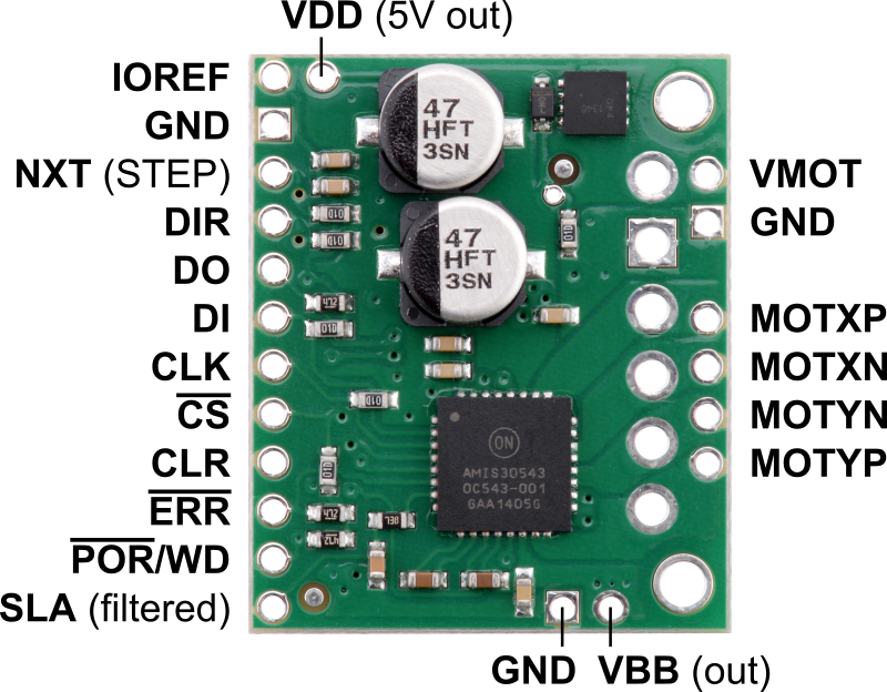 |
AMIS-30543 stepper motor driver carrier, top view with labeled pinout. |
|---|
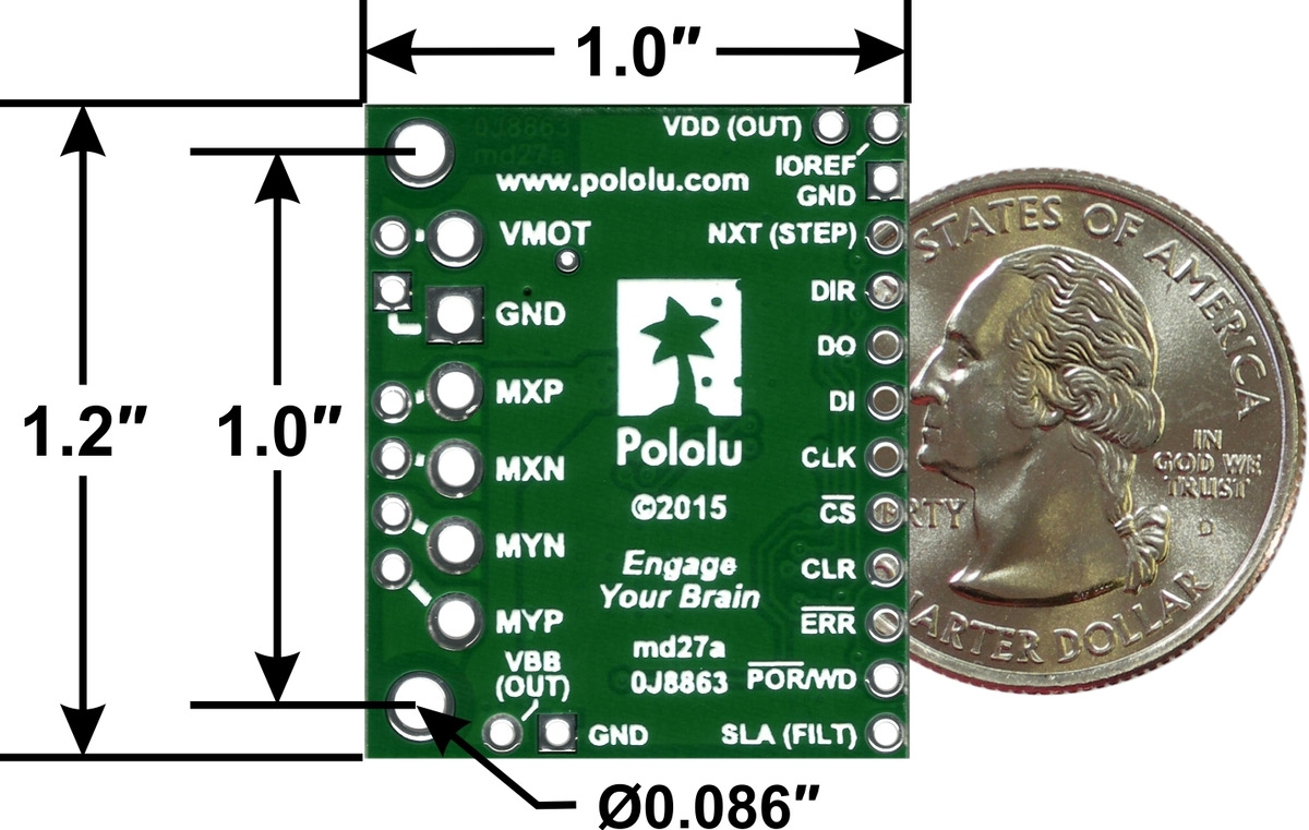 |
AMIS-30543 stepper motor driver carrier, bottom view with dimensions. |
|---|
 |
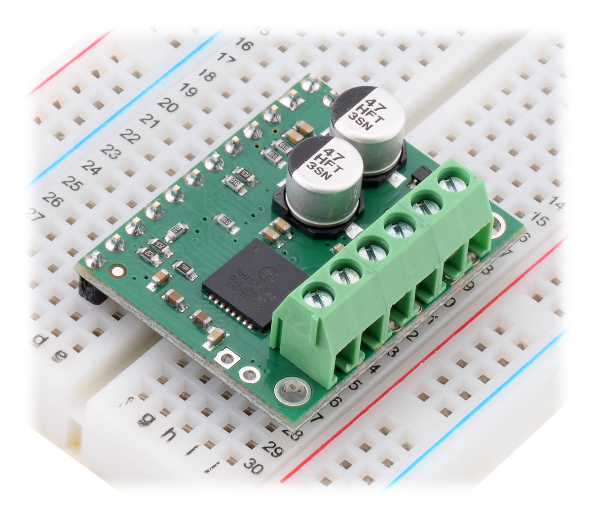
AMIS-30543 stepper motor driver carrier assembled with included header pins facing up. |
|---|
 |
AMIS-30543 stepper motor driver carrier assembled for use with a breadboard (with IOREF=VDD). |
|---|
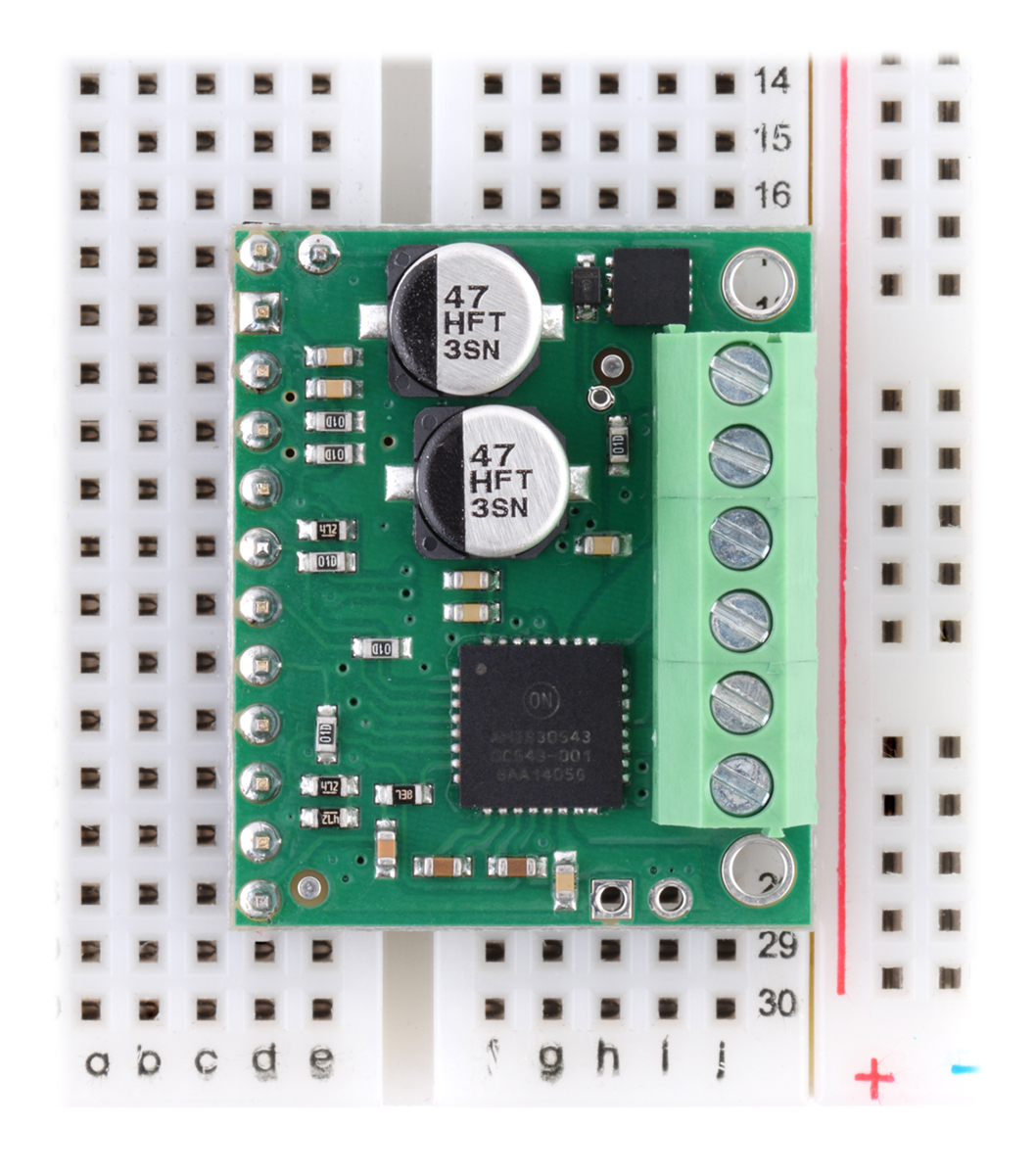 |
AMIS-30543 stepper motor driver carrier assembled for use with a breadboard (with IOREF=VDD). |
|---|
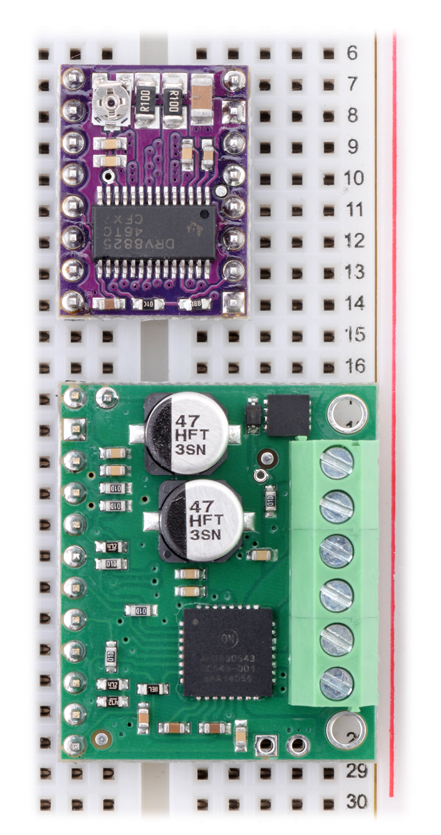 |
AMIS-30543 stepper motor driver carrier next to the popular Pololu A4988/DRV88xx carrier form factor for size comparison. |
|---|
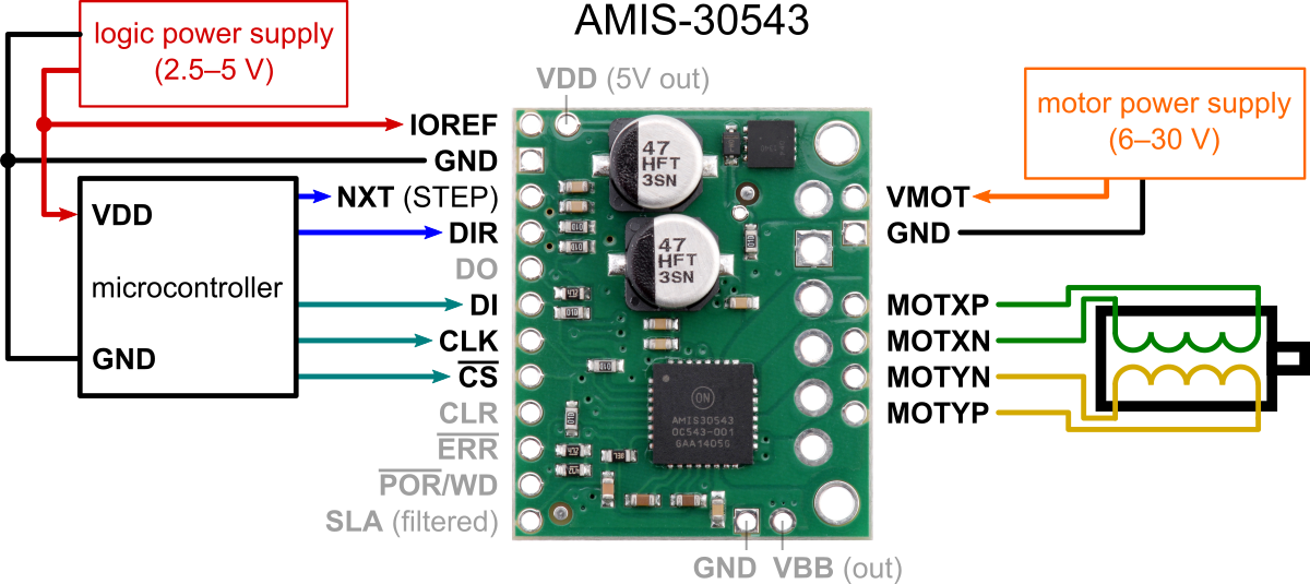 |
Minimal wiring diagram for connecting a microcontroller to an AMIS-30543 stepper motor driver carrier. |
|---|
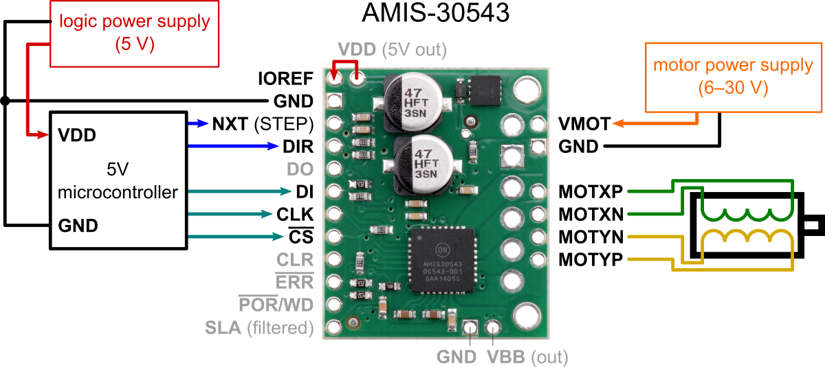 |
Minimal wiring diagram for connecting a microcontroller with a logic voltage of 5 V to an AMIS-30543 stepper motor driver carrier. |
|---|
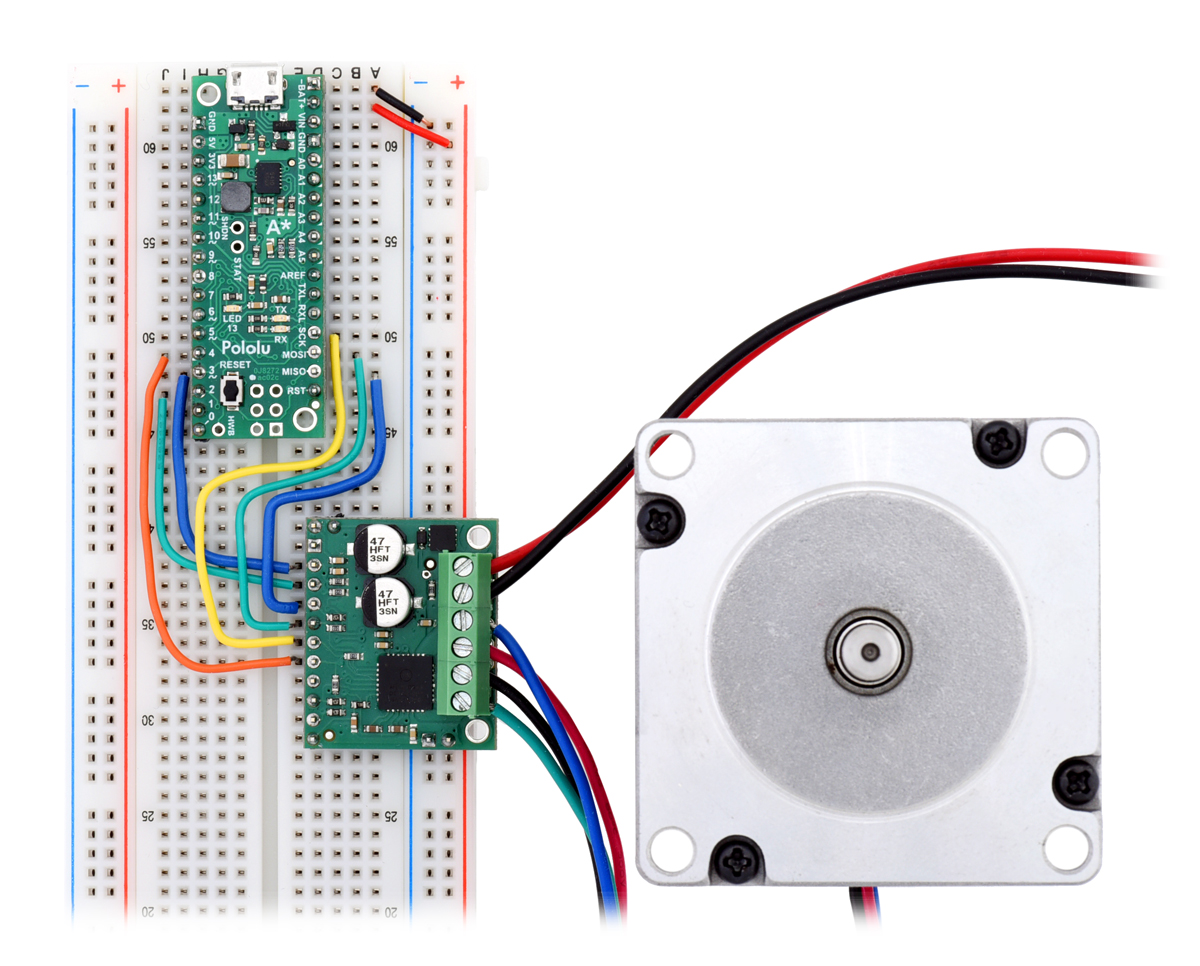 |
Controlling an AMIS-30543 stepper motor driver carrier with an Arduino-compatible #3104 A-Star 32U4 Mini SV. |
|---|
 |
AMIS-30543 stepper motor driver carrier schematic diagram. |
|---|
|
AMIS-30543 stepper motor driver carrier, bottom view with dimensions. |
|---|
This product is a carrier board or breakout board for ON Semiconductor’s AMIS-30543 Micro-Stepping Motor Driver; we therefore recommend careful reading of the AMIS-30543 datasheet (495k pdf) before using this product. This stepper motor driver lets you control one bipolar stepper motor at up to 3 A output current per coil (see the Power Dissipation Considerations section below for more information). Here are some of the board’s key features:
Note: This driver needs to be enabled and configured through its SPI interface on power up, so your microcontroller must be capable of acting as an SPI master (either with an SPI peripheral or software SPI).
|
This product ships with all surface-mount components—including the AMIS-30543 driver IC—installed as shown in the product picture. However, soldering is required for assembly of the included through-hole parts. The following through-hole parts are included:
The 0.1″ male header can be broken or cut into smaller pieces as desired and soldered into the smaller through-holes. These headers are compatible with solderless breadboards, 0.1″ female connectors, and our premium and pre-crimped jumper wires. The terminal blocks can be soldered into the larger holes to allow for convenient temporary connections of unterminated power and stepper motor wires. You can also solder your motor leads and other connections directly to the board for the most compact installation.
|
|
|
| PIN | Description |
|---|---|
| VMOT | Reverse-protected 6 V to 30 V board power supply connection. Note: Available VDD current is reduced for input voltages under 8 V, and sleep mode is not available for input voltages under 9 V. |
| VBB | This pin gives access to the motor power supply after the reverse-voltage protection MOSFET (see the board schematic below). It can be used to supply reverse-protected power to other components in the system. It is generally intended as an output, but it can also be used to supply board power. |
| GND | Ground connection points for the motor power supply and control ground reference. |
| MOTXP | Motor output: “positive” end of phase X coil. |
| MOTXN | Motor output: “negative” end of phase X coil. |
| MOTYP | Motor output: “positive” end of phase Y coil. |
| MOTYN | Motor output: “negative” end of phase Y coil. |
| VDD (5V OUT) | The board is powered by an internal 5V regulator, and this pin gives access to the regulated 5 V output. This can be used to supply the neighboring IOREF pin when using this board in 5V systems, and it can be used to power an external microcontroller. When VMOT is over 8 V, approximately 30 mA is available for external components; when VMOT is less than 8 V, the available current drops to less than 10 mA. |
| IOREF | All of the board signal outputs (except SLA) are open-drain outputs that are pulled up to IOREF, so this pin should be supplied with the logic voltage of the controlling system (e.g. 3.3V for use in 3.3V systems). For convenience, it can be connected to the neighboring VDD pin when it is being used in a 5V system. |
| NXT | Changes on this input move the motor current one step up or down in the translator table (even when the motor is disabled). The edge that triggers the step depends on the NXT-polarity configuration bit, which can be changed through the SPI interface (rising edge by default). |
| DIR | Input that determines the direction of rotation. The direction can also be controlled through the SPI interface. |
| DO | SPI data output. (This pin is also often referred to as “MISO”.) |
| DI | SPI data input. (This pin is also often referred to as “MOSI”.) |
| CLK | SPI clock input. |
| CS | SPI chip select input. Logic transitions on this pin are required for SPI communication, even if this is the only device on the SPI bus. |
| CLR | Chip reset input. A logic high on this input clears all internal registers, except in sleep mode. |
| ERR | Error output. This pin drives low to indicate that an error condition has occurred. The specific error can be determined by using the SPI interface to check the error flags. |
| POR/WD | Power-on reset/watch dog function output. This pin provides an active-low signal that can be used as a reset input for an external microcontroller. |
| SLA (filtered) | SLA (speed and load angle) output after a low-pass filter. The result is an analog voltage between 0 V and 5 V that indicates the level of the back-EMF voltage of the motor. This signal can be used for stall detection or closed-loop control of the torque and speed based on the load angle. Note: Since the output of this pin ranges from 0 V to 5 V regardless of IOREF, extra precautions should be taken when connecting this pin to a 3.3V device (such as passing it through an appropriate voltage divider). |
|
Minimal wiring diagram for connecting a microcontroller to an AMIS-30543 stepper motor driver carrier. |
|---|
While the AMIS-30543 allows control of a stepper motor through a simple step (NXT) and direction (DIR) interface, it first needs to be enabled and configured through its SPI interface. This means that the controlling microcontroller must be capable of acting as an SPI master (either with an SPI peripheral or software SPI), and it must be connected to the DI, CLK, and CS pins. While the DO and ERR pins are not required to use this driver, it is generally a good practice to use them to monitor for error conditions.
|
Minimal wiring diagram for connecting a microcontroller with a logic voltage of 5 V to an AMIS-30543 stepper motor driver carrier. |
|---|
The AMIS-30543 has an internal 5 V regulator that can be used to supply IOREF in cases where the board is being used in 5 V systems. This internal regulator can also be used to supply the external microcontroller’s logic voltage if the regulator can deliver the required current, in which case there would be a wire from the AMIS-30543 VDD to the microcontroller VDD in the above diagram, and the “logic power supply” box would not be present.
|
Controlling an AMIS-30543 stepper motor driver carrier with an Arduino-compatible #3104 A-Star 32U4 Mini SV. |
|---|
If you are new to the AMIS-30543 or stepper motors in general, our AMIS-30543 Arduino library can help you get started. The library provides basic functions for configuring and operating the driver using an Arduino or Arduino-compatible controller. It also provides access to many of the driver’s advanced features and includes example sketches that show you how to use them.
The AMIS-30543 driver IC has a maximum current rating of 3 A per coil, but the actual current you can deliver depends on how well you can keep the IC cool. The carrier’s printed circuit board is designed to draw heat out of the IC, but to supply more than approximately 1.8 A per coil continuously, a heat sink or other cooling method is required. However, it is possible to use the SPI-configurable current limit to selectively deliver higher currents than this for short durations without overheating the driver.
This product can get hot enough to burn you long before the chip overheats. Take care when handling this product and other components connected to it.
Please note that measuring the current draw at the power supply will generally not provide an accurate measure of the coil current. Since the input voltage to the driver can be significantly higher than the coil voltage, the measured current on the power supply can be quite a bit lower than the coil current (the driver and coil basically act like a switching step-down power supply). Also, if the supply voltage is very high compared to what the motor needs to achieve the set current, the duty cycle will be very low, which also leads to significant differences between average and RMS currents.
|
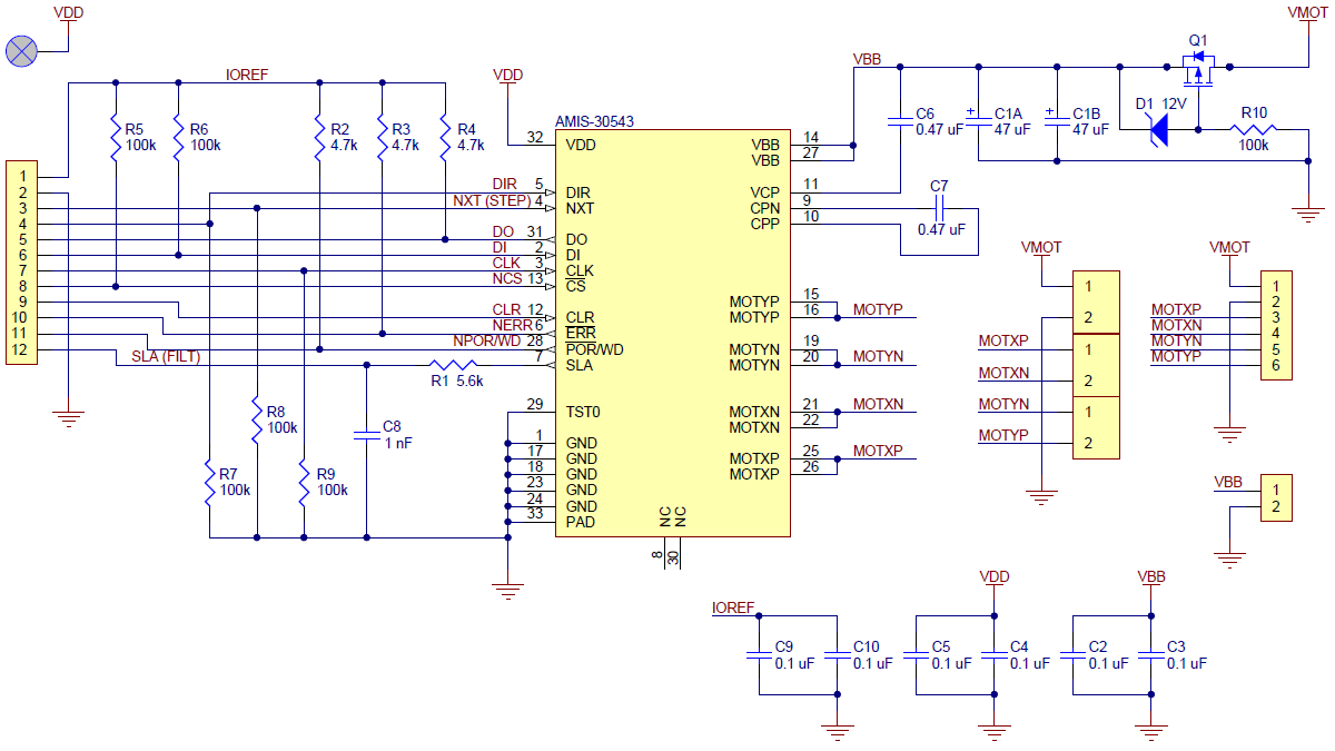
AMIS-30543 stepper motor driver carrier schematic diagram. |
|---|
This diagram is also available as a downloadable pdf: AMIS-30543 stepper motor driver carrier schematic (231k pdf)
| Size: | 1.0″ × 1.2″ |
|---|---|
| Weight: | 4.0 g1 |
| Minimum operating voltage: | 6 V2 |
|---|---|
| Maximum operating voltage: | 30 V |
| Continuous current per phase: | 1.8 A3 |
| Maximum current per phase: | 3 A4 |
| Minimum logic voltage: | 2.5 V |
| Maximum logic voltage: | 5.5 V |
| Microstep resolutions: | full, 1/2, 1/4, 1/8, 1/16, 1/32, 1/64, 1/128 |
| Reverse voltage protection?: | Y |
| PCB dev codes: | md27a |
|---|---|
| Other PCB markings: | 0J8863 |
Printable schematic diagram of the AMIS-30543 Motor Driver Carrier.
This DXF drawing shows the locations of all of the board’s holes.
This application note from ON Semiconductor explains how to use the Speed and Load Angle (SLA) output to build accurate stall-detection and torque-adaptive algorithms.
An Arduino library for controlling the AMIS-30543 micro-stepping stepper motor driver.
ON Semiconductor product page for the AMIS-30543 microstepping stepper motor driver, where you can find the latest datasheet, application notes, and additional resources.
Yes. To avoid damaging your stepper motor, you want to avoid exceeding the rated current, which is 600 mA in this instance. All of our stepper motor drivers let you limit the maximum current, so as long as you set the limit below the rated current, you will be within spec for your motor, even if the voltage exceeds the rated voltage. The voltage rating is just the voltage at which each coil draws the rated current, so the coils of your stepper motor will draw 600 mA at 3.9 V. By using a higher voltage along with active current limiting, the current is able to ramp up faster, which lets you achieve higher step rates than you could using the rated voltage.
If you do want to use a lower motor supply voltage for other reasons, consider using our DRV8834 or STSPIN-220 low-voltage stepper motor drivers.
Yes, you do! Setting the current limit on your stepper motor driver carrier is essential to making sure that it runs properly. An appropriate current limit also ensures that your motor is not allowed to draw more current than it or your driver can handle, since that is likely to damage one or both of them.
Setting the current limit on our AMIS-30543 stepper motor driver carrier is done through its SPI interface (this is very different from our A4988, DRV8825, DRV8824, DRV8834, DRV8880, and TB67S249FTG stepper motor driver carriers, which have their current limits set through their on-board potentiometers). The AMIS-30543 defaults to its lowest possible current limit (132 mA) when it is first enabled; you will need to set this to an appropriate value for your stepper motor before your system will work properly. The AMIS-30543 data sheet (495k pdf) has more information on how to set the current limit through the SPI interface, and our AMIS-30543 Arduino library includes an example sketch showing how to implement this in software.
Measuring the current draw at the power supply does not necessarily provide an accurate measure of the coil current. Since the input voltage to the driver can be significantly higher than the coil voltage, the measured current on the power supply can be quite a bit lower than the coil current (the driver and coil basically act like a switching step-down power supply). Also, if the supply voltage is very high compared to what the motor needs to achieve the set current, the duty cycle will be very low, which also leads to significant differences between average and RMS currents: RMS current is what is relevant for power dissipation in the chip but many power supplies won’t show that. You should base your assessment of the coil current on what the limit has been set to (through the SPI interface) or by measuring the actual coil currents.
While the AMIS-30543 driver IC is rated for up to 3 A (peak) per coil, the chip by itself will overheat at lower currents. We have found that it generally requires a heat sink to deliver more than approximately 1.8 A per coil, but this number depends on factors such as ambient temperature and air flow. For example, sealing three driver carriers in close proximity in a small box will cause them to overheat at lower currents than a unit by itself in open air. It is worth noting that it is possible to use the SPI-configurable current limit to selectively deliver higher currents for short durations without overheating the driver.
This new board is a Pololu carrier for ON Semiconductor’s AMIS-30543 Micro-Stepping Motor Driver, which is a high-performance stepper motor driver...