

This is a merged information page for Item #2855.
View normal product page.
Pololu item #:
2855
Brand:
Pololu
Status:
Active and Preferred

| Output voltage | Typical max output current1 | Input voltage range2 |
|---|---|---|
| 12 V | 2.2 A | 12.7 V – 36 V |
Note 1: At 24 V in. Actual achievable maximum continuous output current is a function of input voltage and is limited by thermal dissipation. See the output current graphs on the product pages for more information.
Note 2: Minimum input voltage is subject to dropout voltage considerations; see the dropout voltage section of product pages for more information.
Alternatives available with variations in these parameter(s): output voltage Select variant…
 Compare all products in D24V22Fx Step-Down Voltage Regulators.
|
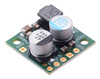
Pololu 12V, 2.2A Step-Down Voltage Regulator D24V22F12. |
|---|
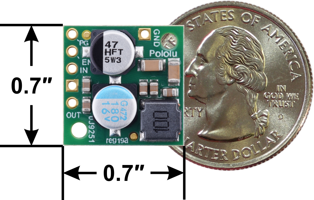 |
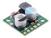
Pololu Step-Down Voltage Regulator D24V22Fx, top view with dimensions. |
|---|
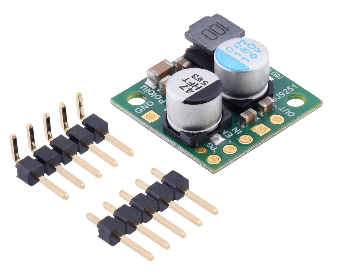 |
Pololu Step-Down Voltage Regulator D24V22Fx with included hardware. |
|---|
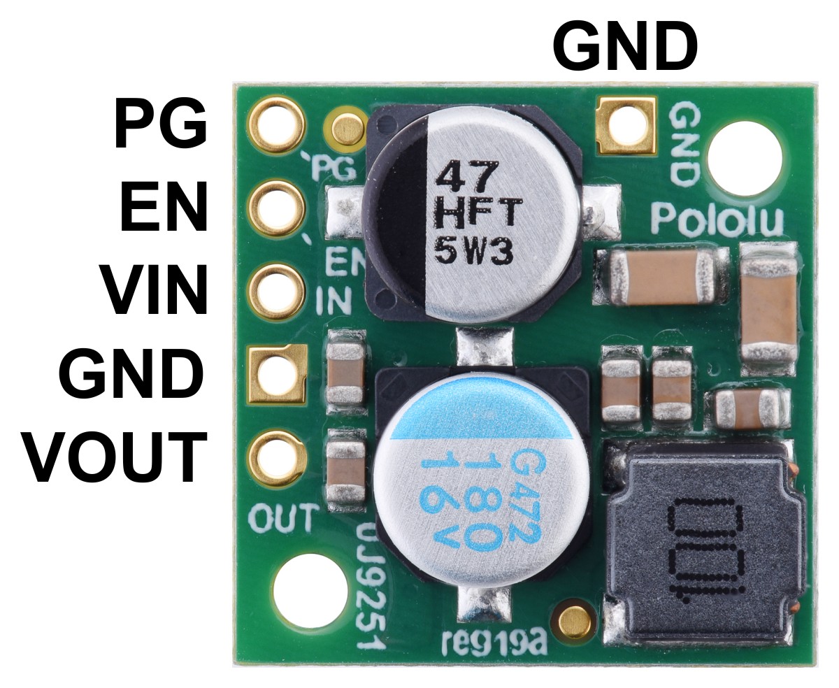 |
Pololu Step-Down Voltage Regulator D24V22Fx, top view with labeled pinout. |
|---|
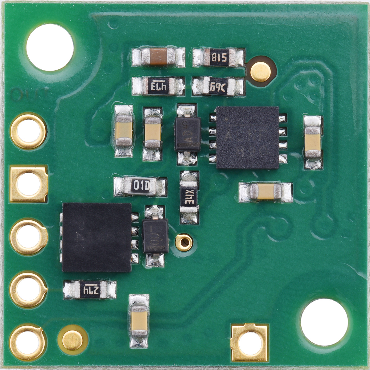 |
Pololu Step-Down Voltage Regulator D24V22Fx, bottom view. |
|---|
 |
Pololu Step-Down Voltage Regulator D24V22Fx, side view. |
|---|
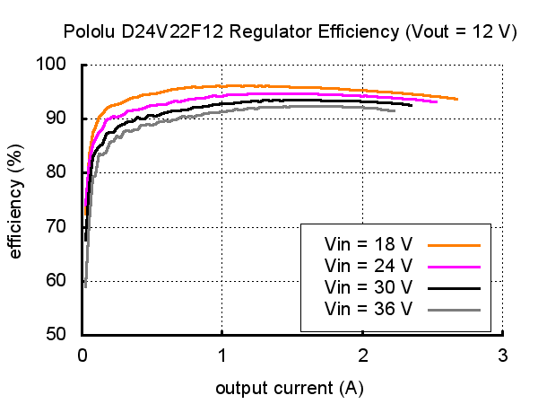 |
Typical efficiency of Pololu 12V, 2.2A Step-Down Voltage Regulator D24V22F12. |
|---|
 |
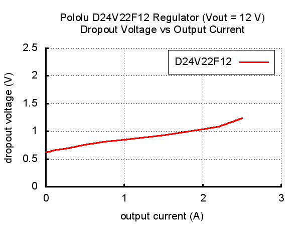
Typical dropout voltage of Pololu 12V, 2.2A Step-Down Voltage Regulator D24V22F12. |
|---|
|
The D24V22Fx family of step-down voltage regulators generates lower output voltages from input voltages as high as 36 V. They are synchronous switching regulators (also called switched-mode power supplies (SMPS) or DC-to-DC converters) with typical efficiencies of 85% to 95%, which is much more efficient than linear voltage regulators, especially when the difference between the input and output voltage is large. These regulators can typically support continuous output currents between 1.4 A and 2.6 A, though the actual available output current is a function of the input voltage and efficiency (see the Typical efficiency and Maximum continuous output current sections below). In general, the available output current is a little higher for the lower-voltage versions than it is for the higher-voltage versions, and it decreases as the input voltage increases.
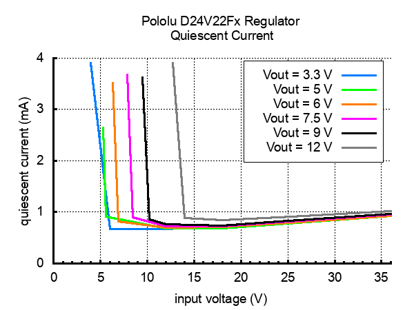
These regulators have a typical quiescent (no load) current draw of around 1 mA, and an enable pin can be used to put the boards in a low-power state that reduces the quiescent current to approximately 5 µA to 10 µA per volt on VIN.
The modules have built-in reverse-voltage protection, short-circuit protection, a thermal shutdown feature that helps prevent damage from overheating, and a soft-start feature that reduces inrush current.
Several different fixed output voltages are available:
The different voltage versions of this regulator all look very similar, so you should consider adding your own distinguishing marks or labels if you will be working simultaneously with multiple versions. This product page applies to all versions of the D24V22Fx family.
The D24V22Fx family is intended to replace our older D24V25Fx family of step-down voltage regulators. The two designs have the same size and similar current capabilities and input voltage ranges, but they do not have the same pinout and are based on different internal circuits, so there are fundamental differences in operation. In particular, these newer D24V22Fx regulators have much lower dropout voltages and provide a “power good” signal, and the newer design allows for higher output voltages (e.g. 12 V).
For higher-power alternatives, please consider our D36V28Fx family of step down regulators that can handle current between 2 A and 4 A and take input voltages up to 50 V.
We manufacture these boards in-house at our Las Vegas facility, which gives us the flexibility to make these regulators with customized components to better meet the needs of your project. For example, if you have an application where the input voltage will always be below 20 V and efficiency is very important, we can make these regulators a bit more efficient at high loads by replacing the 40V reverse voltage protection MOSFET with a 20V one. We can also customize the output voltage. If you are interested in customization, please contact us.
These buck regulators have five main connection points for five different electrical nodes: power good (PG), enable (EN), input voltage (VIN), ground (GND), and output voltage (VOUT). The board also features a second ground connection point off the main row of connections that might be convenient for applications where you are soldering wires directly to the board rather than using it in a breadboard.
|
The input voltage, VIN, powers the regulator. Voltages between 4 V and 36 V can be applied to VIN, but for versions of the regulator that have an output voltage higher than 4 V, the effective lower limit of VIN is VOUT plus the regulator’s dropout voltage, which varies approximately linearly with the load (see below for a graph of dropout voltages as a function of the load).
The output voltage, VOUT, is fixed and depends on the regulator version: the D24V22F3 version outputs 3.3 V, the D24V22F5 version outputs 5 V, the D24V22F6 version outputs 6 V, the D24V22F7 version outputs 7.5 V, the D24V22F9 version outputs 9 V, and the D24V22F12 version outputs 12 V.
The regulator is enabled by default: a 270 kΩ pull-up resistor on the board connects the EN pin to reverse-protected VIN. The EN pin can be driven low (under 1 V) to put the board into a low-power state. The quiescent current draw in this sleep mode is dominated by the current in the pull-up resistor from EN to VIN and by the reverse-voltage protection circuit, which altogether will draw between 5 µA and 10 µA per volt on VIN when EN is held low. If you do not need this feature, you should leave the EN pin disconnected.
The “power good” indicator, PG, is an open-drain output that goes low when the regulator’s output voltage falls below around 85% of the nominal voltage and becomes high-impedance when the output voltage rises above around 90%. An external pull-up resistor is required to use this pin.
|
|
The five main connection points are labeled on the top of the PCB and are arranged with a 0.1″ spacing for compatibility with solderless breadboards, connectors, and other prototyping arrangements that use a 0.1″ grid. Either the included 5×1 straight male header strip or the 5×1 right angle male header strip can be soldered into these holes. For the most compact installation, you can solder wires directly to the board.
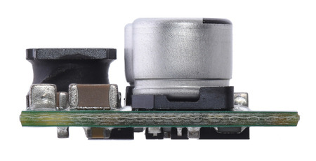 |
Pololu Step-Down Voltage Regulator D24V22Fx, side view. |
|---|
The board has two 0.086″ (2.18 mm) diameter mounting holes intended for #2 or M2 screws. The mounting holes are at opposite corners of the board and are separated by 0.52″ (13.21 mm) both horizontally and vertically. For all the board dimensions, see the dimension diagram (204k pdf).
The efficiency of a voltage regulator, defined as (Power out)/(Power in), is an important measure of its performance, especially when battery life or heat are concerns. This family of switching regulators typically has an efficiency of 85% to 95%, though the actual efficiency in a given system depends on input voltage, output voltage, and output current. See the efficiency graph below for more information.
 |
The dropout voltage of a step-down regulator is the minimum amount by which the input voltage must exceed the regulator’s target output voltage in order to ensure the target output can be achieved. For example, if a 5 V regulator has a 1 V dropout voltage, the input must be at least 6 V to ensure the output is the full 5 V. Generally speaking, the dropout voltage increases as the output current increases. The graph below shows the dropout voltage at different output currents for the D24V22F12.
 |
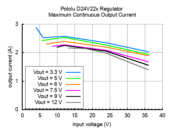
The maximum achievable output current of these regulators varies with the input voltage but also depends on other factors, including the ambient temperature, air flow, and heat sinking. The graph below shows maximum output currents that these regulators can deliver continuously at room temperature in still air and without additional heat sinking.
 |
During normal operation, this product can get hot enough to burn you. Take care when handling this product or other components connected to it.
The quiescent current is the current the regulator uses just to power itself, and the graph below shows this for the different regulator versions as a function of the input voltage. The module’s EN input can be driven low to put the board into a low-power state where it typically draws between 5 µA and 10 µA per volt on VIN.
 |
| Size: | 0.7″ × 0.7″ × 0.31″1 |
|---|---|
| Weight: | 2.3 g1 |
| Minimum operating voltage: | 12.7 V2 |
|---|---|
| Maximum operating voltage: | 36 V |
| Continuous output current: | 1.9 A3 |
| Output voltage: | 12 V |
| Reverse voltage protection?: | Y |
| Maximum quiescent current: | 4 mA4 |
| PCB dev codes: | reg19a |
|---|---|
| Other PCB markings: | 0J9251 |
No FAQs available.
This post is a few weeks late, but I am following up on my original D24V22F12 12V regulator introduction to let you know that we now have 3.3 V,...
We are pleased to introduce our new 12 V, 2.2 A switching regulator, the inaugural member of the D24V22Fx family of step down voltage regulators....