

This is a merged information page for Item #2851.
View normal product page.
Pololu item #:
2851
Brand:
Pololu
Status:
Rationed (Active)

This small synchronous switching step-down (or buck) regulator takes an input voltage of up to 38 V and efficiently reduces it to 5 V. The board measures only 0.7″ × 0.8″, but it allows a typical continuous output current of up to 5 A. Typical efficiencies of 85% to 95% make this regulator well suited for high-power applications like powering motors or servos. High efficiencies are maintained at light loads by dynamically changing the switching frequency, and an optional shutdown pin enables a low-power state with a current draw of a few hundred microamps.
 Compare all products in Step-Down (Buck) Voltage Regulators.
|
Pololu 5V, 5A Step-Down Voltage Regulator D24V50F5. |
|---|
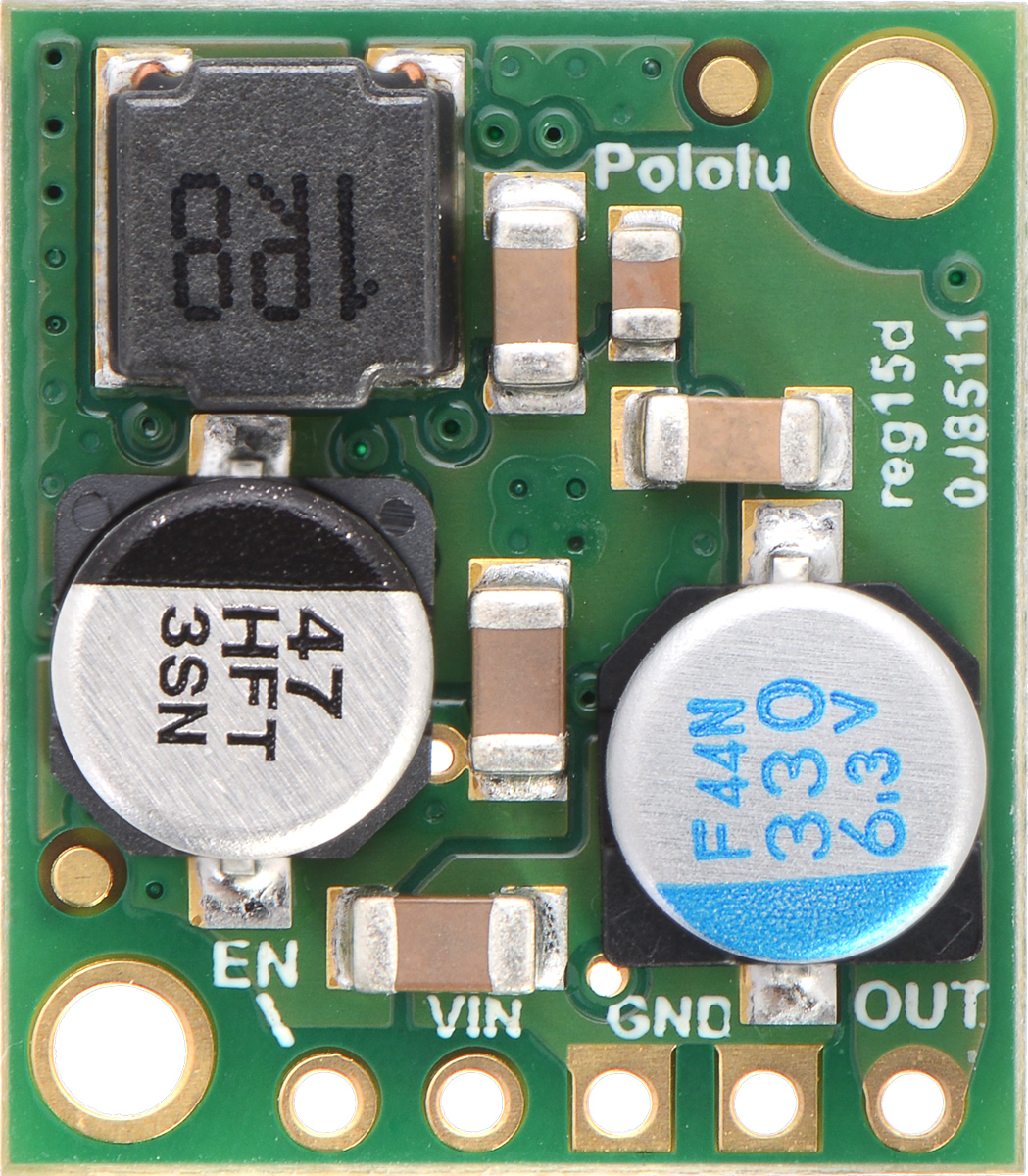 |
Pololu 5V, 5A Step-Down Voltage Regulator D24V50F5, top view. |
|---|
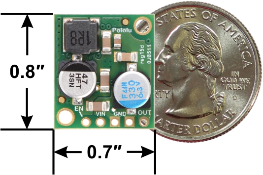 |
Pololu 5A Step-Down Voltage Regulator D24V50F5, top view with dimensions. |
|---|
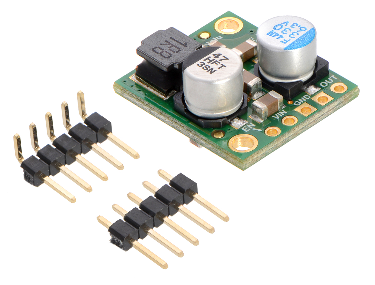 |
Pololu 5A Step-Down Voltage Regulator D24V50F5 with included hardware. |
|---|
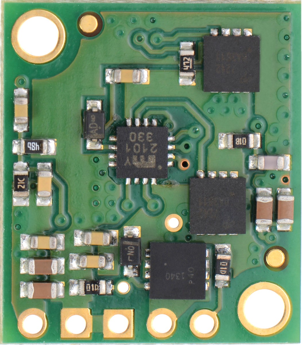 |
Pololu 5A Step-Down Voltage Regulator D24V50F5, bottom view. |
|---|
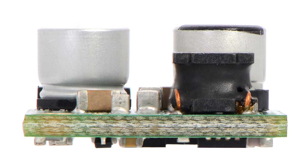 |
Pololu 5A Step-Down Voltage Regulator D24V50F5, side view. |
|---|
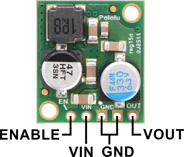 |
Pololu 5A Step-Down Voltage Regulator D24V50F5, top view with labeled pinout. |
|---|
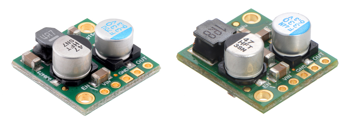 |
Side-by-side comparison of the 2.5 A D24V25Fx (left) and 5 A D24V50F5 (right) step-down voltage regulators. |
|---|
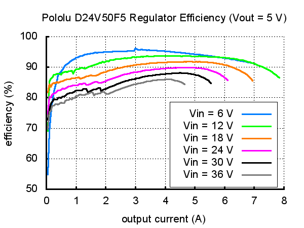 |
Typical efficiency of Pololu 5V, 5A Step-Down Voltage Regulator D24V50F5. |
|---|
 |
Typical dropout voltage of Pololu 5V, 5A Step-Down Voltage Regulator D24V50F5. |
|---|
|
This step-down (buck) regulator generates a fixed 5 V output from input voltages up to 38 V. It is a switching regulator (also called a switched-mode power supply (SMPS) or DC-to-DC converter) and has a typical efficiency between 85% to 95%, which is much more efficient than linear voltage regulators, especially when the difference between the input and output voltage is large. The available output current is a function of the input voltage and efficiency (see the Typical Efficiency and Output Current section below), but the output current can typically be as high as 5 A.
At light loads, the switching frequency automatically changes to maintain high efficiencies. The regulator has a typical quiescent current draw of less than 1 mA, and the ENABLE pin can be used to put the board in a low-power state that reduces the quiescent current to approximately 10 µA to 20 µA per volt on VIN.
This regulator has built-in reverse-voltage protection, short-circuit protection, a thermal shutdown feature that helps prevent damage from overheating, a soft-start feature that reduces inrush current, and an under-voltage lockout.
For lower-power applications, consider our D30V30Fx family of step-down voltage regulators; these are slightly smaller, pin-compatible versions of this regulator with typical maximum output current of 2.5 A. For higher-voltage alternatives, consider our D42V55Fx family of step-down voltage regulators, which can operate from voltages as high as 60 V and deliver higher output currents. Both of these regulator families are available in several different voltage versions.
|
Side-by-side comparison of the 2.5 A D24V25Fx (left) and 5 A D24V50F5 (right) step-down voltage regulators. |
|---|
For a 5 V regulator with even more output current, consider our D24V90F5 step-down voltage regulator, which has a typical maximum output current of 9 A. This higher-power regulator also has a few additional features, like a “power good” signal and the ability to lower its output voltage, and it includes optional terminal blocks for easy removable connections.
This buck regulator has five connection points for four different connections: enable (EN), input voltage (VIN), 2x ground (GND), and output voltage (VOUT).
|
The input voltage, VIN, powers the regulator and can be supplied with voltages up to 38 V. The effective lower limit of VIN is VOUT plus the regulator’s dropout voltage, which varies approximately linearly with the load from around 700 mV to around 1.5 V (see below for a graph of the dropout voltages as a function of the load).
The regulator is enabled by default: a 100 kΩ pull-up resistor on the board connects the ENABLE pin to reverse-protected VIN. The ENABLE pin can be driven low (under 0.6 V) to put the board into a low-power state. The quiescent current draw in this sleep mode is dominated by the current in the pull-up resistor from ENABLE to VIN and by the reverse-voltage protection circuit, which will draw between 10 µA and 20 µA per volt on VIN when ENABLE is held low. If you do not need this feature, you should leave the ENABLE pin disconnected.
|
|
The five connection points are labeled on the top of the PCB and are arranged with a 0.1″ spacing for compatibility with solderless breadboards, connectors, and other prototyping arrangements that use a 0.1″ grid. Either the included 5×1 straight male header strip or the 5×1 right angle male header strip can be soldered into these holes. For the most compact installation, you can solder wires directly to the board.
 |
Pololu 5A Step-Down Voltage Regulator D24V50F5, side view. |
|---|
The board has two 0.086″ mounting holes intended for #2 or M2 screws. The mounting holes are at opposite corners of the board and are separated by 0.53″ horizontally and 0.63″ vertically.
The efficiency of a voltage regulator, defined as (Power out)/(Power in), is an important measure of its performance, especially when battery life or heat are concerns. As shown in the graph below, these switching regulators have an efficiency of 85% to 95% for most combinations of input voltage and load.
|
The maximum achievable output current of the board depends on many factors, including the ambient temperature, air flow, heat sinking, and the input and output voltage.
During normal operation, this product can get hot enough to burn you. Take care when handling this product or other components connected to it.
The over-current limit of the regulator operates on a combination of current and temperature: the current threshold decreases as the regulator temperature goes up. However, there might be some operating points at low input voltages and high output currents (well over 5 A) where the current is just under the limit and the regulator might not shut off before damage occurs. If you are using this regulator in an application where the input voltage is near the lower limit and the load could exceed 5 A for sustained periods (more than five seconds), consider using additional protective components such as fuses or circuit breakers.
The dropout voltage of a step-down regulator is the minimum amount by which the input voltage must exceed the regulator’s target output voltage in order to ensure the target output can be achieved. For example, if a 5 V regulator has a 1 V dropout voltage, the input must be at least 6 V to ensure the output is the full 5 V. The following graph shows the dropout voltages for the D24V50F5 regulator as a function of the output current:
|
The regulator generally operates at a switching frequency of around 600 kHz, but the frequency drops when encountering a light load to improve efficiency. This could make it harder to filter out noise on the output caused by switching.
| Size: | 0.7″ × 0.8″ × 0.35″1 |
|---|---|
| Weight: | 3.0 g1 |
| Minimum operating voltage: | 6 V2 |
|---|---|
| Maximum operating voltage: | 38 V |
| Continuous output current: | 5 A3 |
| Output voltage: | 5 V |
| Reverse voltage protection?: | Y |
| Maximum quiescent current: | 0.8 mA4 |
| PCB dev codes: | reg15d |
|---|---|
| Other PCB markings: | 0J8511 |
This DXF drawing shows the locations of all of the board’s holes.
No FAQs available.

For the second year in a row, Team Hitchin Hackspace and their robot, Tito-Stretch, placed 4th overall in the Pi Wars! They did this at the...

Congratulations to Team Anveshak from IIT Madras, who took first place at the 2019 Indian Rover Challenge! The IRC is a robotics and space...

Remember the post I wrote two weeks ago about our tiny D24V25F5 voltage regulator and some of the testing that we did on it? Well, we were so...