This is a merged information page for Item #1366.
View normal product page.
Pololu item #:
1366
Brand:
Pololu
Status:
Rationed (Active and Preferred)

This powerful motor controller makes basic control of a brushed DC motor easy, with quick configuration over USB using our free software. It supports five control interfaces: USB, TTL serial, I²C, analog voltage (potentiometer), and hobby radio control (RC). This version offers a wide 6.5 V to 30 V operating range and can deliver continuous output currents up to 25 A without a heat sink. Male headers and terminal blocks are included but not soldered, allowing for custom installations.
Alternatives available with variations in these parameter(s): version Select variant…
 Compare all products in Pololu Simple Motor Controllers or Pololu G2 Simple Motor Controllers.
|
High-Power Simple Motor Controller G2 18v25. |
|---|
 |
High-Power Simple Motor Controller G2 18v25. |
|---|
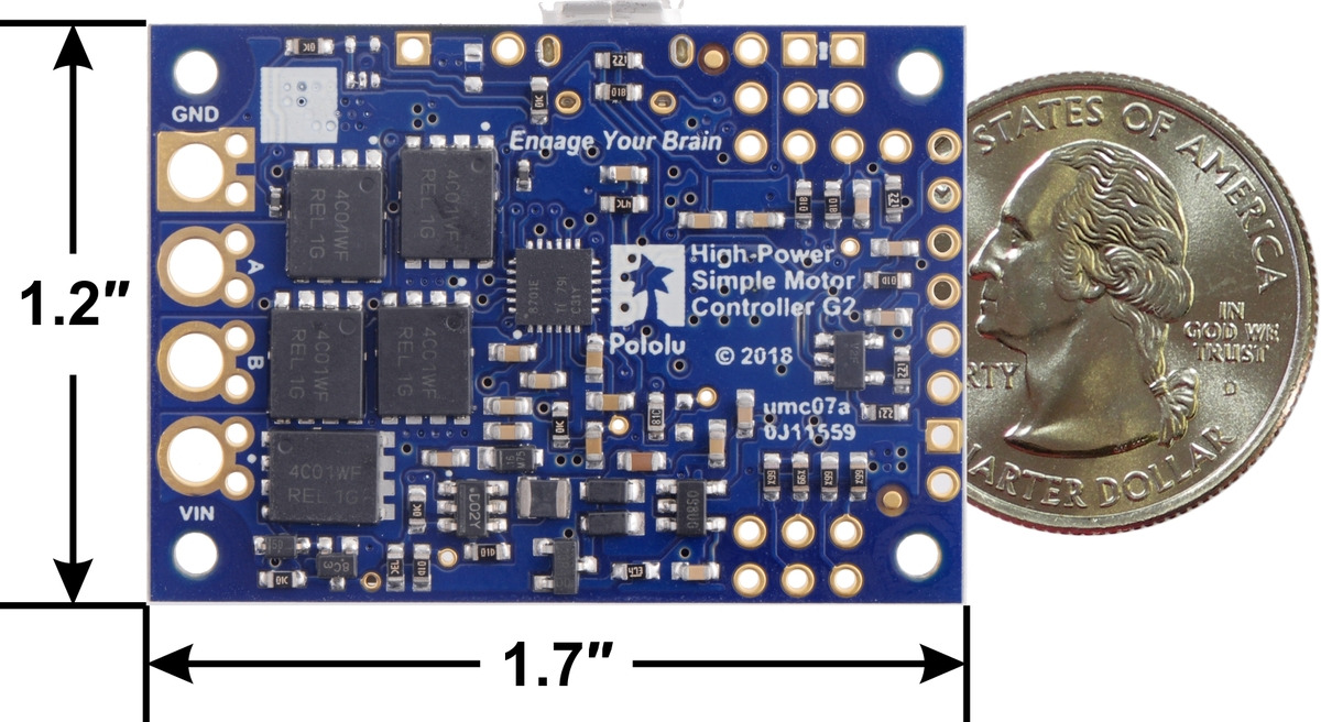 |
High-Power Simple Motor Controller G2 18v25, bottom view with dimensions. |
|---|
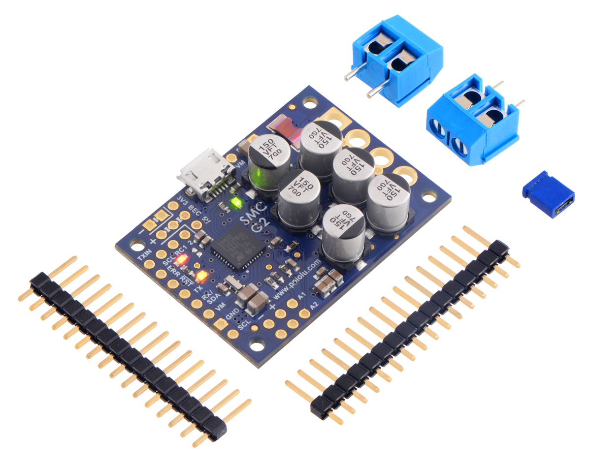 |
High-Power Simple Motor Controller G2 18v25 with included hardware. |
|---|
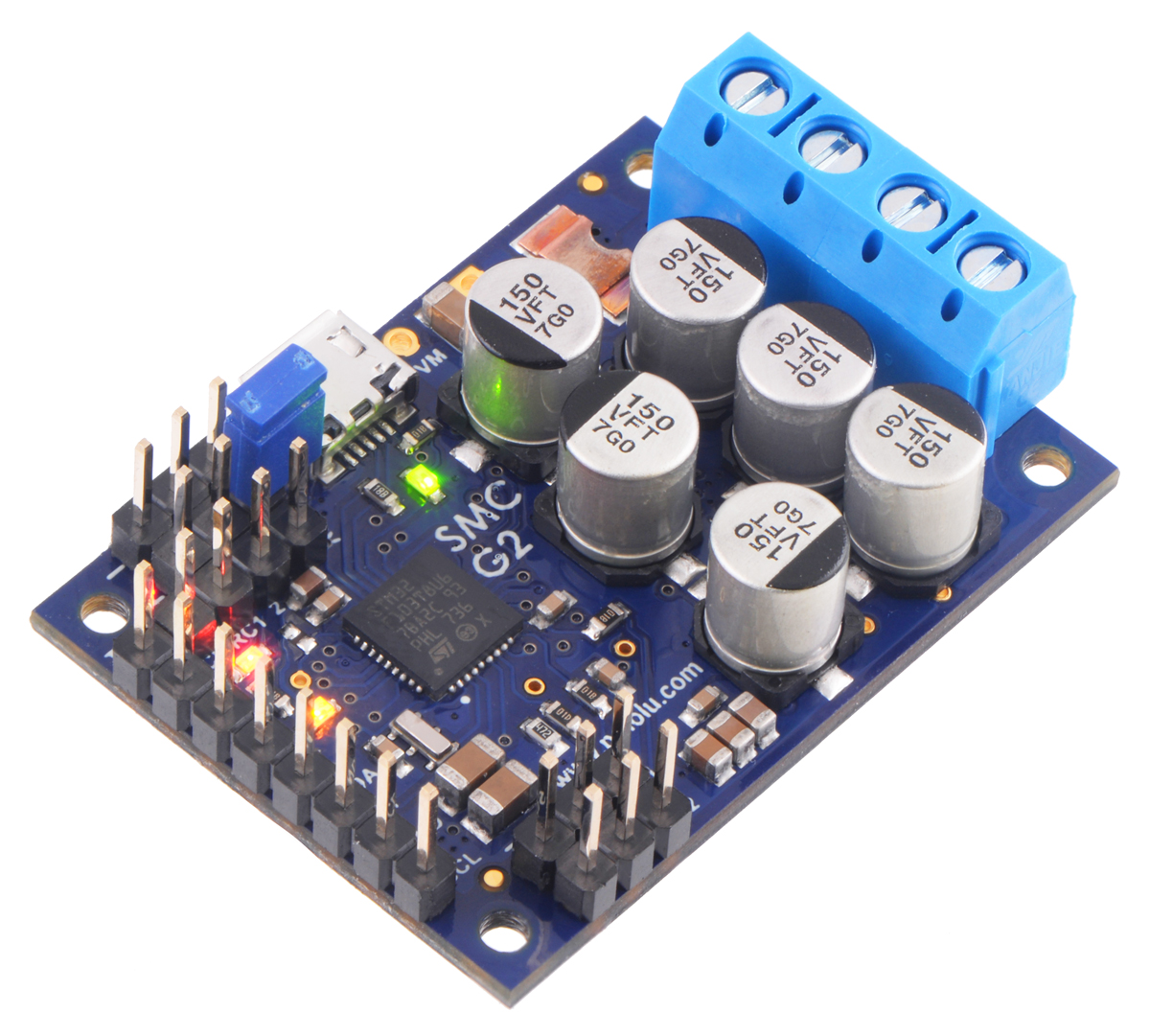 |
High-Power Simple Motor Controller G2 18v25 with connectors soldered. |
|---|
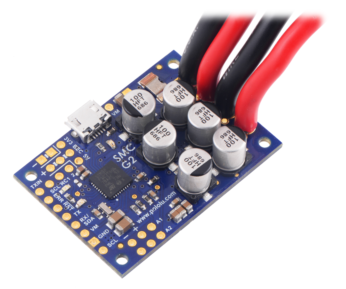 |
High-Power Simple Motor Controller G2 18v25 or 24v19 with thick wires soldered. |
|---|
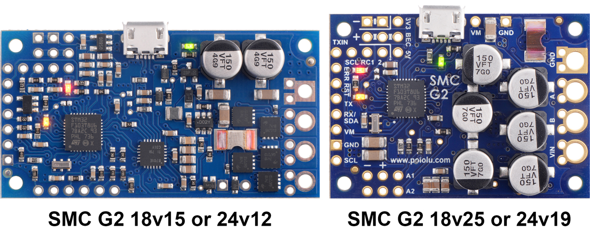 |
Side-by-side comparison of the different G2 Simple Motor Controllers. |
|---|
|
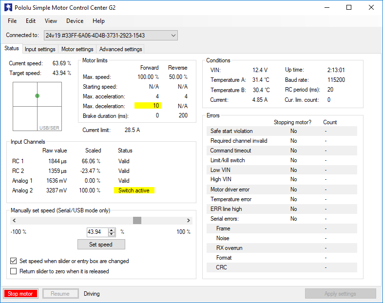
The Simple Motor Controllers are versatile, general-purpose single-channel motor controllers for brushed, DC motors. Wide operating voltage ranges and the ability to deliver up to several hundred watts in a small form factor make these controllers suitable for many motor control applications. With a variety of supported interfaces—USB for direct connection to a computer, TTL serial and I²C for use with embedded systems, RC hobby servo pulses for use as an RC-controlled electronic speed control (ESC), and analog voltages for use with a potentiometer or analog joystick—and a wide array of configurable settings, these motor controllers make it easy to add basic control of brushed DC motors to a variety of projects. A free configuration utility for Windows simplifies initial setup of the device and allows for in-system testing and monitoring of the controller via USB.
The table below lists the all of the members of the Simple Motor Controller family and shows the key differences among them. Note that the information on this page is specific to the newer SMC G2s, which can generally be used as drop-in replacements for the original SMCs with green PCBs. The original SMCs are not recommended for new designs, and they are only included in the table below for comparison purposes.
| Original versions, not recommended for new designs (included for comparison purposes) |
G2 versions, released November 2018 |
||||||||
 SMC 18v7 |
 SMC 18v15 |
SMC 24v12 |
 SMC 18v25 |
SMC 24v23 |
 SMC G2 18v15 |
 SMC G2 24v12 |
 SMC G2 18v25 |
 SMC G2 24v19 |
|
|---|---|---|---|---|---|---|---|---|---|
| Minimum operating voltage: | 5.5 V | 5.5 V | 5.5 V | 5.5 V | 5.5 V | 6.5 V | 6.5 V | 6.5 V | 6.5 V |
| Recommended max operating voltage: |
24 V(1) | 24 V(1) | 34 V(2) | 24 V(1) | 34 V(2) | 24 V(1) | 34 V(2) | 24 V(1) | 34 V(2) |
| Max nominal battery voltage: |
18 V | 18 V | 28 V | 18 V | 28 V | 18 V | 28 V | 18 V | 28 V |
| Max continuous current (no additional cooling): |
7 A | 15 A | 12 A | 25 A | 23 A | 15 A | 12 A | 25 A | 19 A |
| USB, TTL serial, Analog, RC control: |
 |
|
|
|
|
|
|
|
|
| I²C control: | |
|
|
|
|||||
| Hardware current limiting: | |
|
|
|
|||||
| Reverse voltage protection: | |
|
|
|
|||||
| Dimensions: | 2.1″ × 1.1″ | 2.3″ × 1.2″ | 2.1″ × 1.1″ | 1.7″ × 1.2″ | |||||
| Price: | $157.53 | $161.27 | $169.88 | $201.99 | $204.14 | $135.02 | $135.02 | $165.09 | $165.09 |
| Available with connectors installed? |
Yes | Yes | Yes | No | No | Yes | Yes | No | No |
| 1 30 V absolute max. 2 40 V absolute max. |
|||||||||
 |
The SMC G2 18v25 operates from 6.5 V to 30 V and can deliver a continuous output current of 25 A without a heat sink. Note that 30 V is the absolute maximum for this controller; the maximum recommended operating voltage is 24 V, and the maximum recommended nominal battery voltage is 18 V. For applications using higher voltages (such as 24 V batteries), we recommend the higher-voltage SMC G2 24v12 or SMC G2 24v19.
If you need to identify which version you have, you can just plug it into a computer through USB and the SMC software will tell you. For quick visual identification without a computer, you can distinguish this version from the identically sized SMC G2 24v19 by the number 150 on top of the tall silver electrolytic capacitors.
This version has header pins and terminal blocks included but not soldered, so soldering is required to use it.
|
|
|
The SMC ships with a 0.1″ breakaway male header strip and two 2-pin 5mm terminal blocks. You can solder the terminal blocks to the four large through-holes to make your motor and motor power connections (see our short video on terminal block installation), or you can solder a couple of 2-pin pieces of the 0.1″ header strip into the smaller through-holes above and below these larger holes.
Pieces from the 0.1″ header strip can be soldered into the small holes on the logic connection side of the board to enable use with solderless breadboards, perfboards, or 0.1″ connectors. For the most compact installation, you can just solder wires directly to the holes.
Note: A USB A to Micro-B cable (not included) is required to connect this controller to a computer.
|
|
This video demonstrates the versatility of the Simple Motor Controller by showing how it can be controlled directly from the analog output of a Sharp analog distance sensor—there is no intermediate control board and no programming involved. The unit in the video is one of our original SMCs, but the newer SMC G2s have the same capabilities. For more information on this example, including the SMC settings file and a list of parts used, see our blog post about the demo.
The SMC G2 family features a number of improvements compared to our original Simple Motor Controllers with green PCBs:
The SMC G2 controllers have the same pin arrangements as the original SMCs, so they should be usable as drop-in replacements in typical applications, though note that the minimum operating voltage is a little higher for the G2 versions (6.5 V vs 5.5 V for the originals). The SMC G2 serial protocol is compatible with (and generally a superset of) the original SMC serial protocol, so in most cases, serial interface software running on a microcontroller or computer will not need to be modified to work with a SMC G2.
| Size: | 1.7″ × 1.2″ × 0.42″1 |
|---|---|
| Weight: | 9.7 g1 |
| Motor channels: | 1 |
|---|---|
| Control interface: |
USB; non-inverted TTL serial; I²C; RC servo pulses; analog voltage2 |
| Minimum operating voltage: | 6.5 V |
| Maximum operating voltage: | 30 V3 |
| Continuous output current per channel: | 25 A4 |
| Maximum PWM frequency: | 22.5 kHz |
| Maximum logic voltage: | 3.3 V5 |
| Reverse voltage protection?: | Y |
| Version: | G2 18v25 (30 V max, 25 A max continuous) |
| Connectors soldered?: | N |
| PCB dev codes: | umc07a |
|---|---|
| Other PCB markings: | 0J11559, blank white box |
User’s manual for the Pololu Simple Motor Controller G2.
The Pololu USB SDK contains example code for making your own applications that use native USB to control the Jrk Motor Controller, Maestro Servo Controller, Simple Motor Controller, or USB AVR Programmer.
This DXF drawing shows the locations of all of the board’s holes.
This DXF drawing shows the locations of all of the board’s holes.
The analog input readings on the Simple Motor Controller are updated approximately every 2.3 ms (435 Hz) if the “Ignore pot disconnect” option is selected. If that option is not selected, which is the default, the readings are updated half as frequently.
If no acceleration or deceleration limits are used, the outputs of the motor controller will be updated very quickly (within a few hundred microseconds) after the analog reading is complete. If those limits are enabled, the motor might take up to a millisecond to be updated after the analog reading is complete.

Last week, we released updated (G2) versions of our Simple Motor Controllers. We released our original Simple Motor Controllers just over eight...