LISY300AL Single-Axis Gyro with ±300°/s Range

This gyroscope board is a basic carrier/breakout board for the ST LISY300AL single-axis gyro, which measures rotational motion about the yaw (z) axis with a ±300°/s range and outputs an analog voltage. This board has a 3.3V regulator for easy integration with 5V parts, includes a low-pass filter for noise reduction, and is smaller than competing products, all at a lower price.
| Description | Specs (7) | Pictures (2) | Resources (1) | FAQs (0) | On the blog (0) |
|---|
Note: ST has discontinued the LISY300AL IC, so this product has been discontinued. Please consider our dual-axis gyros as replacements.
 |
Overview
This single-axis gyro is essentially a carrier board or breakout board for the ST LISY300AL MEMS (micro-electro-mechanical systems) gyroscope; we therefore recommend careful reading of the LISY300AL datasheet (176k pdf) before using this product. The LISY300 is a great IC, but its small, leadless package makes it difficult for the typical student or hobbyist to use. The device also operates at 2.7 V to 3.6 V, which can make interfacing difficult for microcontrollers operating at 5 V. This carrier board addresses both issues while keeping the overall size below half a square inch.
Features
- Integrated 3.3V regulator means no extra parts are required for integration into 5V systems.
- Measures rotation speeds from -300 degrees/second to +300 degrees/second.
- Optional power-down input; may be shorted to a neighboring ground pin if the low-power state is not needed.
- Optional embedded self-test input; this is connected to a pull-down resistor on the board to disable it by default.
- Two-stage low-pass filtered output to reduce high-frequency noise.
- Two mounting holes (0.086", intended for #2 screws) for sturdy connection to a robot chassis or project enclosure.
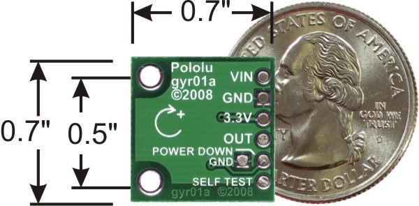
- Small size: 0.7" × 0.7".
Using the sensor
The sensor measures rotation in the plane of the board, as indicated by the arrow on the board silkscreen (shown above).
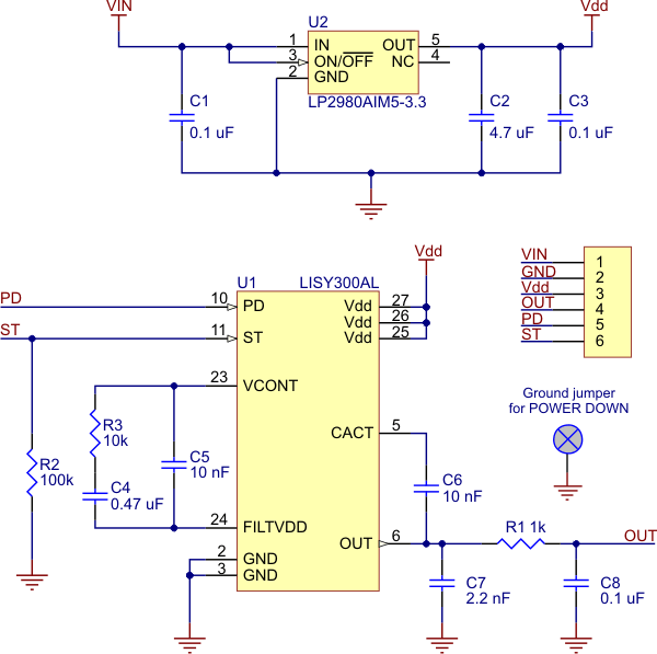
The schematic for the gyroscope carrier is shown below. The device can be powered directly through the Vdd/3.3 V pin using a supply that is within the LISY300AL’s acceptable power supply range of 2.7 V to 3.6 V. Alternatively, the board can be powered by higher voltages, up to 16 V, using the VIN pin, which connects to a low-dropout 3.3 V regulator. In this configuration, the Vdd/3.3 V pin can serve as an output to be used as a reference voltage or power source for other low-power devices (up to around 50 mA, depending on the input voltage).
The power down pin is not connected by default. If a low-power state is not required for your application, use a small piece of wire or solder to make a short between the power down pin and the ground pin next to it. To use the power down pin, your circuit must bring it up to Vdd (typically 3.3 V); in 5 V applications, this can be done by adding a pull-up resistor to the 3.3 V output.
The self-test input is pulled low by default. To activate the self-test feature of the LISY300AL, drive the line to Vdd (the same pull-up trick as above can be used for 5 V applications).
For 5 V microcontroller applications, the power down and self test lines should not be driven high. Instead, the microcontroller I/O pin can emulate an open-drain or open-collector output by alternating between low output and high-impedance (input) states. Put another way, if you are using a 5 V microcontroller, you should make your power down and self test I/O lines inputs and use pull-up to 3.3 V if you want them to be high. It is always safe for you to drive these lines low.
The output is an RC-filtered analog voltage that ranges from 0 to Vdd; with no rotation, the output voltage is typically 1.65 V with Vdd set to 3.3 V. For 5 V applications, the outputs will range from 0 to 3.3 V. The 3.3 V output can be used as a reference for analog-to-digital converters to gain full resolution samples. Otherwise, your conversions will be limited to 66% of the full range (e.g. an 8-bit ADC will yield numbers from 0 to 168).
 |
People often buy this product together with:
 |
TB6612FNG Dual Motor Driver Carrier |
 |
Pololu Carrier with Sharp/Socle GP2Y0D810Z0F Digital Distance Sensor 10cm |
 |
Sharp/Socle GP2Y0A02YK0F Analog Distance Sensor 20-150cm |
Related products


Home | Forum | Blog | Support | Ordering Information | Wish Lists | Distributors | BIG Order Form | About | Contact
© 2001–2024 Pololu Corporation
