Electronics » LEDs » Addressable RGB LEDs Based on the SK6812/WS281x »
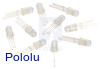
Addressable Through-Hole 8mm RGB LED with Diffused Lens, WS2811 Driver (10-Pack)

This 10-pack of 8 mm through-hole RGB LEDs offers an easy way to add colorful and complex lighting effects to a project. Each diffused LED features an integrated WS2811 driver that operates at 5 V and is controlled through a high-speed one-wire digital interface that allows multiple LEDs to be connected together to form a chain of addressable RGB LEDs.
Alternatives available with variations in these parameter(s): LED diameter Select variant…
 Compare all products in Addressable RGB LEDs Based on the SK6812/WS281x or LEDs or Addressable Through-Hole RGB LEDs.
| Description | Specs (5) | Pictures (4) | Resources (5) | FAQs (0) | On the blog (5) | Distributors (4) |
|---|
Overview
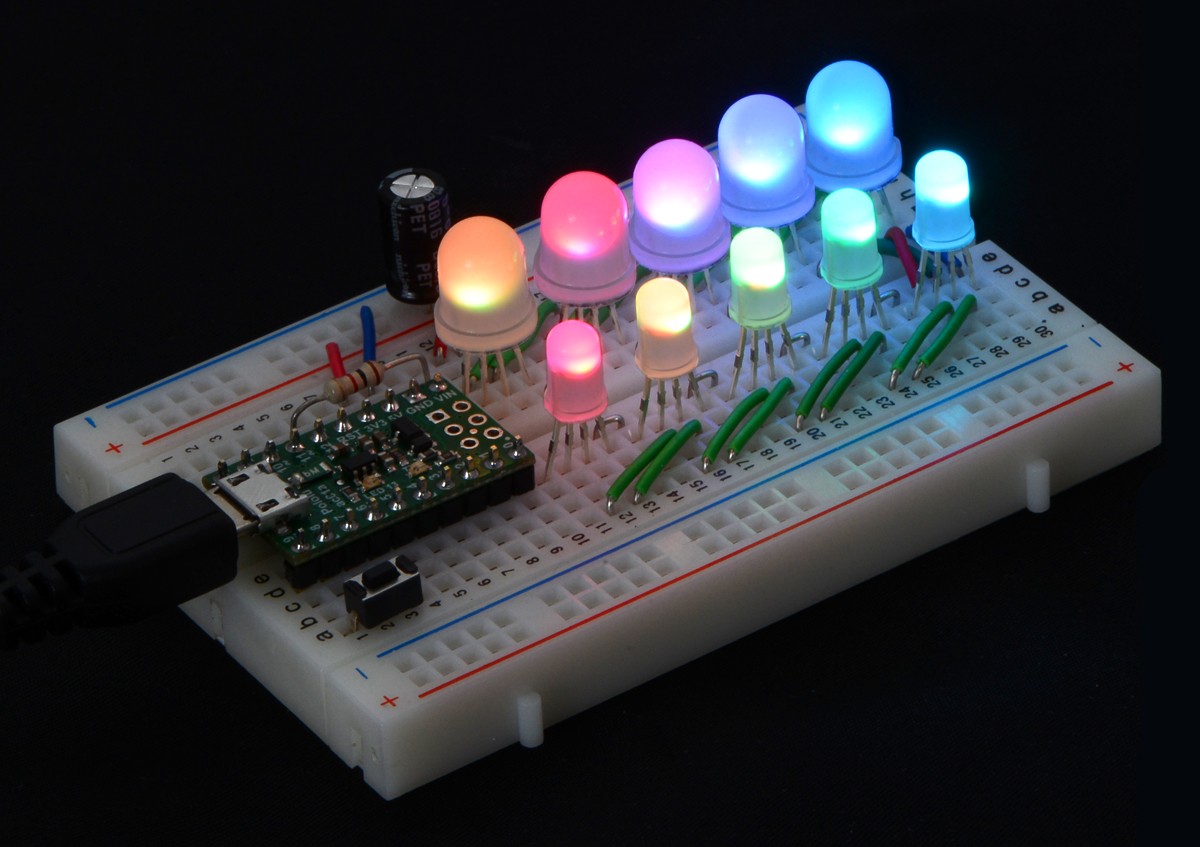 |
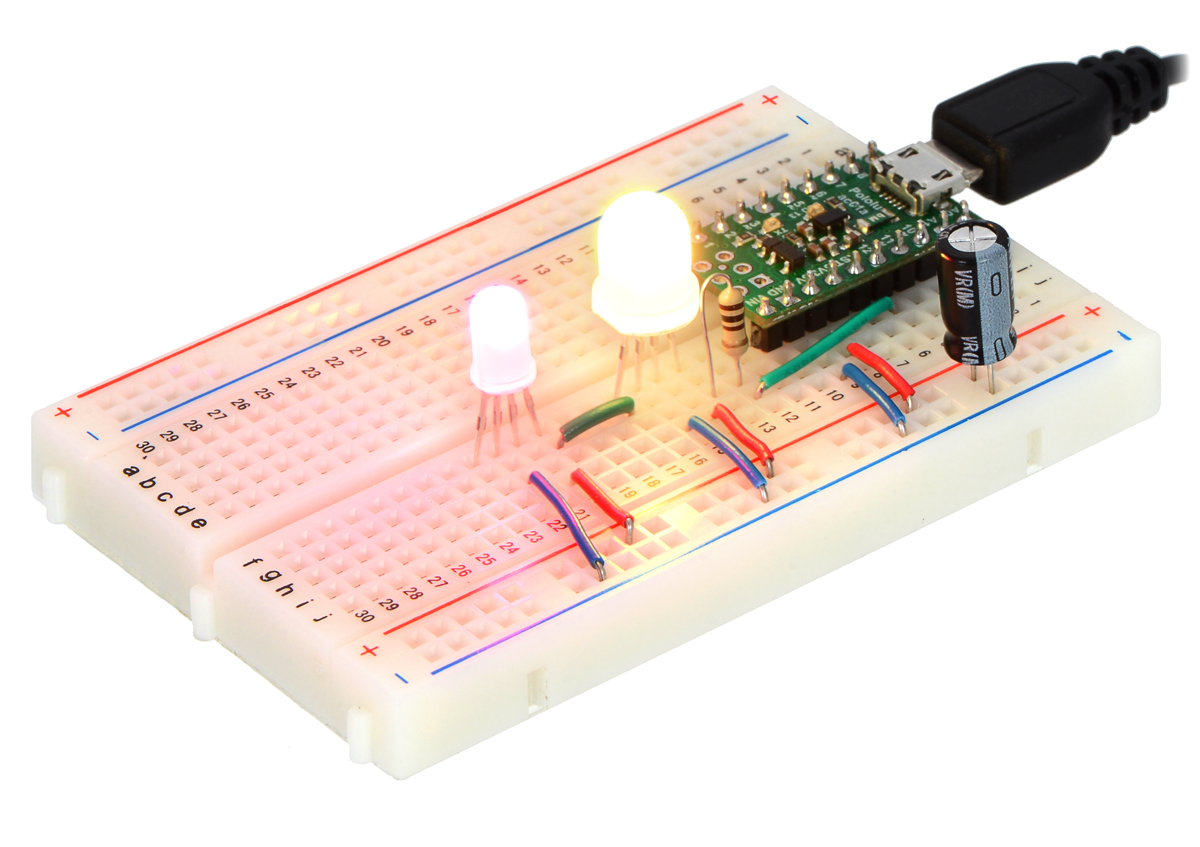
These LED 10-packs are an easy way to add colorful and complex lighting effects to a project. Each RGB LED contains an integrated WS2811 driver that allows it to be controlled with a high-speed one-wire interface (see the bottom of this page for sample code, including an Arduino library for controlling these LEDs). Multiple LEDs can be connected together to form a chain of RGB LEDs, and the entire chain can be controlled from a single microcontroller pin. These are very similar to the LEDs in our addressable RGB LED strips, but with these discrete LEDs you have far more flexibility in how they are arranged. The picture on the right shows a chain of 10 LEDs in a breadboard controlled by an A-Star 32U4 Micro.
We offer these LEDs in two different sizes: 5 mm and 8 mm.
Features and specifications
- One-wire digital control interface
- Can form a chain of individually-addressable RGB LEDs
- 24-bit color control (8-bit PWM per channel); 16.8 million colors per pixel
- 5 V operating voltage
- Draws approximately 50 mA at 5 V with red, green, and blue at full brightness
- Color ordering: red, green, blue
- Example code available for Arduino, AVR, and mbed
Using the LED
Pinout
The LED has 4 pins, as shown in the diagram below:
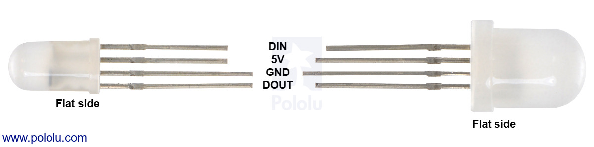 |
The pins can be identified by the length of the leads or by looking for the flat side of the LED.
Connecting the LEDs
The DIN pin is the input signal pin. The DIN pin of the first LED in the chain should be connected to an I/O line of a microcontroller.
The 5V pin supplies power to the LED, and should be connected to a suitable 5 V power supply. The power supply should be capable of supplying enough current for all the LEDs it is powering. Each LED draws approximately 50 mA with all three channels at full brightness.
The GND pin should be connected to the ground pin of the microcontroller that is controlling the LEDs and also the negative terminal of the power supply.
The DOUT pin is optional and allows you to chain multiple LEDs together. It can be connected directly to the DIN pin of the next LED in the chain.
We recommend taking several precautions to protect these LEDs from damage:
- Never supply more than 5 V to the LED.
- Connect a capacitor of at least 10 μF between the ground and power lines.
- Avoid making or changing connections while the circuit is powered.
- Minimize the length of the wires connecting your microcontroller to the LED.
- Follow generally good engineering practices, such as taking precautions against electrostatic discharge (ESD).
- Consider adding a 100 Ω to 1000 Ω resistor between your microcontroller’s data output and the LED to reduce the noise on that line and to avoid accidentally powering the LED through its data input.
Warning: These LEDs can explode if they are pushed beyond their limits. For example, we were able to make an 8 mm LED explode by powering at 6 V and setting it to full brightness for about a minute (though we could not subsequently replicate that result). We strongly recommend you avoid powering these LEDs at voltages over 5 V.
Default Color
After power is applied to these LEDs, they will emit bright blue light until the first color command is received.
Chaining
These LEDs can be chained with each other and also with other LED products that have a similar protocol. In particular, they can be chained with any of our SK6812/WS281x-Based Addressable RGB LEDs. Even though these LEDs use a different color ordering than the WS2812B (RGB instead of GRB), they can still be chained to WS2812B-based products.
Protocol
These LEDs are controlled by a simple, high-speed one-wire protocol on the input signal line. The protocol is documented below.
The default, idle state of the signal line is low. To update the LED colors, you need to transmit a series of high pulses on the signal line. Each high pulse encodes one bit: a short pulse (0.35 μs) represents a zero, while a long pulse (0.9 μs) represents a one. The time between consecutive rising edges should be 1.25μs. After the bits are sent, the signal line should be held low for 50 μs to send a reset command, which makes the new color data take effect.
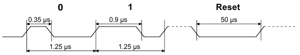 |
SK6812/WS281x RGB data timing diagram. |
|---|
The color of each LED is encoded as three LED brightness values, which must be sent in RGB (red-green-blue) order. Each brightness value is encoded as a series of 8 bits, with the most significant bit being transmitted first, so each LED color takes 24 bits. The first color transmitted applies to the LED that is closest to the control source, while the second color transmitted applies to the next LED in the chain, and so on.
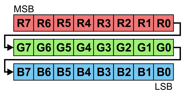 |
24 bits in RGB order represent the color of one LED. |
|---|
To update all the LEDs in the chain, you should send all the colors at once with no pauses. If you send fewer colors than the number of LEDs in the chain, then some LEDs near the end will not be updated. For example, to update 10 LEDs wired in a chain, you would send 240 bits encoded as high pulses and then hold the signal line low for 50 μs.
The high-speed protocol of the driver allows for fast updates; our library for the Arduino below takes about 1.1 ms to update 30 LEDs. However, constant updates are not necessary; the LED can hold its state indefinitely as long as power remains connected.
Implementing the protocol on a microcontroller
 |
Since this LED does not use a standard protocol, a software bit-banging approach is usually needed to control it from a microcontroller. Because of the sub-microsecond timing, the bit-banging code generally needs to be written in assembly or very carefully optimized C, and interrupts will need to be disabled while sending data to the LEDs. If the interrupts in your code are fast enough, they can be enabled during periods where the signal line is low. It is generally not possible to generate the required control signals directly from older, slower microcontroller boards, like the Basic Stamp, or from processors that run full operating systems and can experience multithreading delays, like the Raspberry Pi.
Sample code
To help you get started quickly, we provide sample code for these microcontroller platforms:
- PololuLedStrip Arduino library (also works with our Arduino-compatible A-star modules)
- Example AVR C code
- PololuLedStrip mbed library
Additionally, the Adafruit NeoPixel library for Arduino should work with these LEDs since the NeoPixels are based on the similar WS2812B driver.
People often buy this product together with:
 |
Female Crimp Pins for 0.1" Housings 100-Pack |
 |
Addressable Through-Hole 5mm RGB LED with Diffused Lens, WS2811 Driver (10-Pack) |
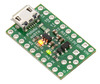 |
A-Star 32U4 Micro |
Related products


Home | Forum | Blog | Support | Ordering Information | Lists | Distributors | BIG Order Form | About | Contact
© 2001–2025 Pololu Corporation
