Electronics » Motion Control Modules » Brushed DC Motor Drivers »
DRV8801 Single Brushed DC Motor Driver Carrier

This tiny breakout board for TI’s DRV8801 provides a modern alternative to classic motor drivers such as the L293D, SN754410, and L298N. It can deliver a continuous 1 A (2.8 A peak) to a single motor and offers a wide operating voltage range of 8 V to 36 V. The DRV8801 features a simple two-pin speed/direction interface, current-sense feedback, and built-in protection against under-voltage, over-current, and over-temperature.

| Description | Specs (12) | Pictures (8) | Resources (6) | FAQs (0) | On the blog (1) | Distributors (39) |
|---|
Note: We have several newer and better motor drivers that we recommend over this DRV8801 carrier, which we no longer recommend for new designs. See the comparison table below for more details.
| DRV8801 carrier compared to newer alternatives | |||||
|---|---|---|---|---|---|
 DRV8801 |
 DRV8876 (QFN) |
 DRV8876 |
 DRV8874 |
 DRV8256E DRV8256P |
|
| Motor channels: | single | single | single | single | single |
| Min. operating voltage: | 8 V | 4.5 V | 4.5 V | 4.5 V | 4.5 V |
| Max. operating voltage: | 36 V | 37 V | 37 V | 37 V | 48 V |
| Max. continuous current(1): | 1 A | 1.1 A | 1.3 A | 2.1 A | 1.9 A |
| Peak current: | 2.8 A | 2 A(2) | 2 A(2) | 4.4 A(2) | 6.4 A |
| Current sense feedback? | 500 mV/A | 2500 mV/A | 2500 mV/A | 1100 mV/A | — |
| Active current limiting: | — | adjustable | adjustable | adjustable | adjustable |
| Size: | 0.6″ × 0.6″ | 0.6″ × 0.7″ | 0.6″ × 0.7″ | 0.6″ × 0.7″ | 0.6″ × 0.6″ |
| 1-piece price: | $15.95 | $7.14 | $8.15 | $11.94 | $14.31 (E) $14.31 (P) |
| 1 Per motor channel, on Pololu carrier board, at room temperature, and without additional cooling. | |||||
| 2 Default current limit; see product descriptions for details. | |||||
Overview
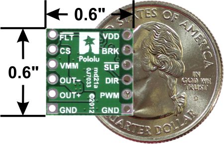 |
DRV8801 single brushed DC motor driver carrier with dimensions. |
|---|
Texas Instruments’ DRV8801 is a tiny H-bridge motor driver IC that can be used for bidirectional control of a single brushed DC motor at 8 V to 36 V. It can supply up to about 1 A continuously and can tolerate peak currents up to 2.8 A for a few seconds, making it a good choice for small motors that run on a wide range of voltages. Since this board is a carrier for the DRV8801, we recommend careful reading of the DRV8801 datasheet. The board ships populated with all of its SMD components, including the DRV8801.
For a more powerful driver with a similar operating voltage range, please consider our MAX14870 carrier. For a dual-channel driver with a similar operating voltage range, please consider our A4990 carrier or A4990 Arduino shield. For lower-voltage alternatives to the DRV8801, please consider our DRV8838 single-channel motor driver carrier and DRV8833 and DRV8835 dual motor driver carriers.
Features
- Drives a single brushed DC motor
- Motor supply voltage: 8 V to 36 V
- Logic supply voltage: 3.3 V to 6.5 V
- Output current: 1 A continuous (2.8 A peak)
- Simple interface requires only two I/O lines (one for direction and another for speed)
- Current sense output proportional to motor current (approx. 500 mV per A)
- Inputs are 3V- and 5V-compatible
- Under-voltage lockout and protection against over-current and over-temperature
Using the motor driver
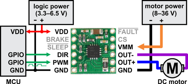 |
Minimal wiring diagram for connecting a microcontroller to a DRV8801 single brushed DC motor driver carrier. |
|---|
In a typical application, power connections are made on one side of the board and control connections are made on the other. Aside from motor and power connections, the only required pins are DIR and PWM (called PHASE and ENABLE in the DRV8801 datasheet, respectively). A PWM signal can be applied to the PWM/ENABLE pin to achieve variable speed control in the direction determined by the state of the DIR/PHASE pin. The carrier board pulls PWM low by default, so the driver is only enabled when this pin is supplied with a high signal. The DIR pin does not have a defined default state, which means outputs could behave erratically if the DIR pin is left disconnected while the PWM pin is high.
The BRAKE pin determines whether the motor brakes or coasts when PWM pin is low (this pin is called MODE1 in the DRV8801 datasheet). The carrier board pulls it high, which corresponds to braking (both motor outputs are shorted together through ground). Setting the BRAKE pin low sets the outputs to coast whenever the PWM pin is low (both motor outputs are off). We generally recommend leaving this high while supplying a PWM signal to the PWM pin to get drive-brake (or “slow-decay”) operation, as this typically provides a more linear relationship between PWM duty cycle and motor speed than drive-coast (or “fast-decay”), and it can result in better performance at low duty cycles. The following truth table shows how the PWM, DIR, and BRAKE pins affect the driver outputs:
| DRV8801 Truth Table | |||||
|---|---|---|---|---|---|
| PWM/ENABLE | DIR/PHASE | BRAKE/MODE1 | OUT+ | OUT- | operating mode |
| PWM | 1 | 1 | PWM (H/L) | L | forward/brake at speed PWM % |
| PWM | 0 | 1 | L | PWM (H/L) | reverse/brake at speed PWM % |
| L | X | 1 | L | L | brake low (outputs shorted to ground) |
| PWM | 1 | 0 | PWM (H/OPEN) | PWM (L/OPEN) | forward/coast at speed PWM % |
| PWM | 0 | 0 | PWM (L/OPEN) | PWM (H/OPEN) | reverse/coast at speed PWM % |
| L | X | 0 | OPEN | OPEN | coast (outputs off) |
Note: When braking, the driver brakes low because the DRV8801’s MODE2 pin is pulled low on the carrier board. The MODE2 pin is not exposed to the user.
The SLEEP pin is pulled high on the board through a 10k resistor and can be left disconnected if you do not want to use the low-power sleep mode of the DRV8801.
The FAULT pin is an open-drain output that is driven low by the chip whenever an over-current, over-temperature, or under-voltage condition occurs. The carrier board includes a pull-up resistor on this pin, so no external pull-up is necessary. Note that the FAULT pin is a status-only signal that does not affect device functionality, so a low FAULT signal does not necessarily mean the driver outputs are disabled. For example, the driver will start operating normally once the motor supply voltage is above 8 V, but the FAULT output will be low until the motor supply voltage reaches approximately 12 V. Please see the datasheet for more information about how the DRV8801 responds to and reports faults.
The CS pin outputs an analog voltage proportional to the motor current (approximately 500 mV per A).
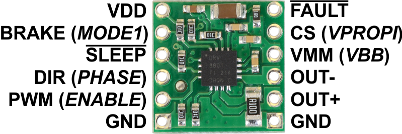
Pinout
 |
| PIN | Default State | Description |
|---|---|---|
| VMM/VBB | 8 V to 36 V motor power supply connection. This pin called VBB in the DRV8801 datasheet. | |
| VDD | 3.3 V to 6.5 V logic power supply connection. This pin is only used to power the FAULT, SLEEP, and BRAKE pull-up resistors on the carrier board. (The DRV8801 has its own internal logic voltage regulator.) | |
| GND | Ground connection points for the motor and logic power supplies. | |
| OUT+ | H-bridge output +. | |
| OUT- | H-bridge output -. | |
| DIR/PHASE | undefined | Logic input for controlling motor direction. |
| PWM/ENABLE | LOW | Logic input for enabling the driver outputs/controlling motor speed. A PWM signal can be applied to this pin. |
| BRAKE/MODE1 | HIGH | Logic input for controlling whether the driver brakes low or coasts when PWM pin is low. A logic high results in braking (slow-decay through ground). |
| SLEEP | HIGH | Logic input that puts the DRV8801 into a low-power sleep mode when low. |
| FAULT | Logic output that drives low when a fault occurs. The carrier board pulls this pin up to VDD. | |
| CS/VPROPI | Analog voltage output proportional to motor current (500 mV per A). Note: this pin will output 0 V whenever the driver is in slow-decay mode (i.e., when BRAKE/MODE1 is HIGH). |
Real-world power dissipation considerations
The DRV8801 datasheet recommends a maximum continuous current of 2.8 A. However, the chip by itself will overheat at lower currents. For example, in our tests at room temperature with no forced air flow, the chip was able to deliver 2.8 A for a few seconds, 1.4 A for approximately 30 s, and 1.2 A for almost two minutes before the chip’s thermal protection kicked. A continuous current of 1 A per channel was sustainable for many minutes without triggering a thermal shutdown. The actual current you can deliver will depend on how well you can keep the motor driver cool. The carrier’s printed circuit board is designed to draw heat out of the motor driver chip, but performance can be improved by adding a heat sink. Our tests were conducted at 100% duty cycle; PWMing the motor will introduce additional heating proportional to the frequency.
This product can get hot enough to burn you long before the chip overheats. Take care when handling this product and other components connected to it.
Included hardware
|
|

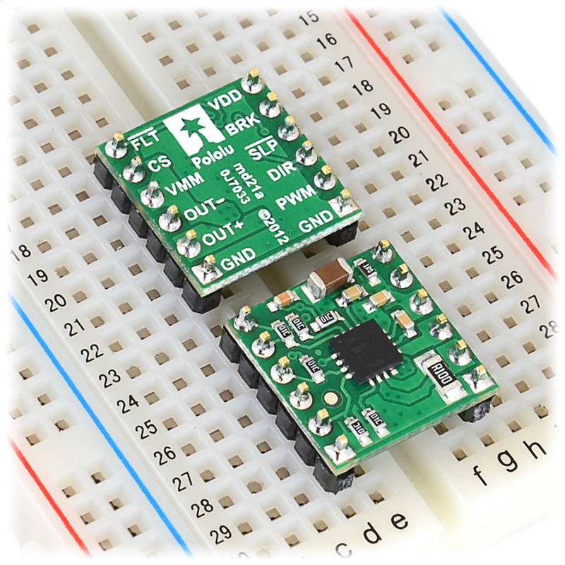
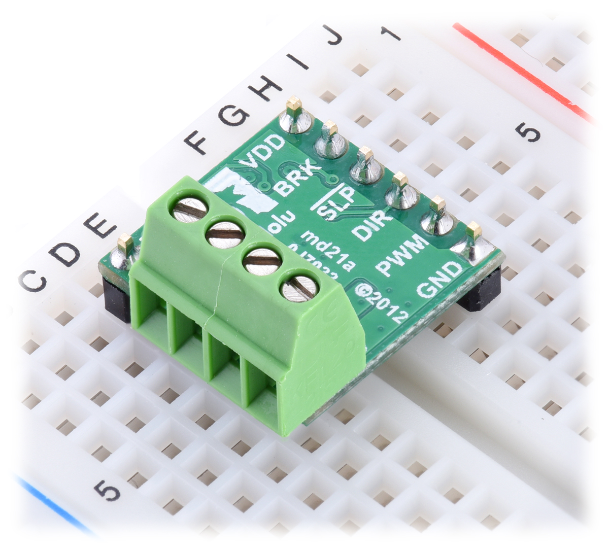
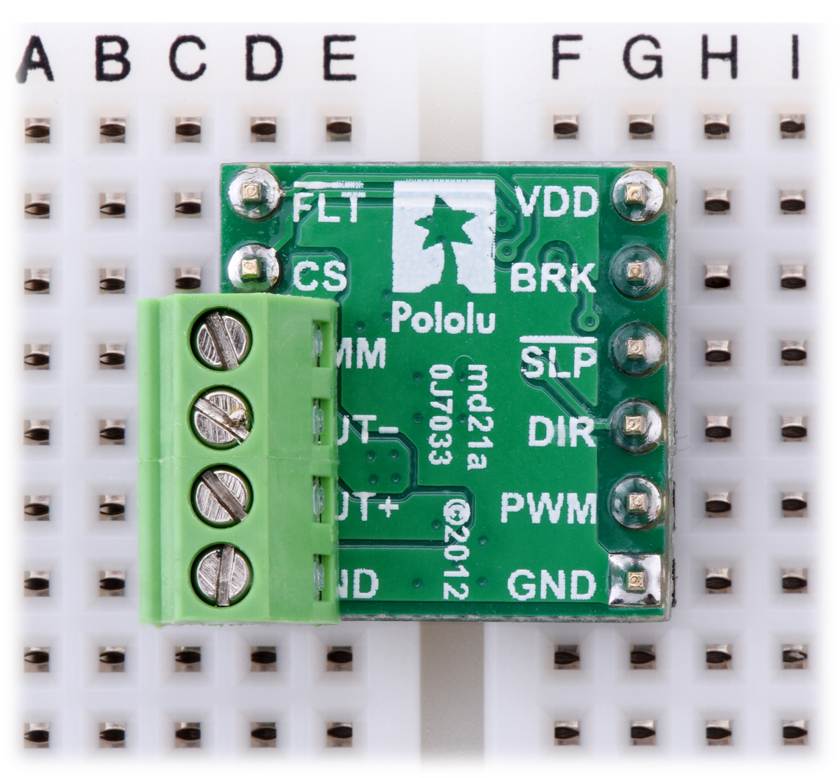
Breakaway 0.1″ male headers are included with the DRV8801 motor driver carrier, which can be soldered in to use the driver with perfboards, breadboards, or 0.1″ female connectors. (The headers might ship as a single larger strip that can be broken into smaller pieces.) The right picture above shows the two possible board orientations when used with these header pins (parts visible or silkscreen visible). You can also solder your motor leads and other connections directly to the board, or you could use 0.1″ terminal blocks (not included) to allow for easy, temporary connections:
|
|
Schematic
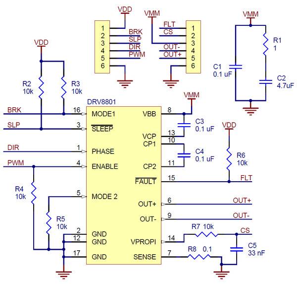 |
Schematic diagram for the DRV8801 single brushed DC motor driver carrier. |
|---|
This schematic is also available as a downloadable pdf (157k pdf)
Related products


Home | Forum | Blog | Support | Ordering Information | Lists | Distributors | BIG Order Form | About | Contact
© 2001–2026 Pololu Corporation
