Support » Pololu TReX Jr User’s Guide » 3. Getting Started »
3.b. Signal Connections
RC/analog signals should connect to the interior of the three channel columns; this connection is represented by the white wire in the figure below.
The middle column is connected to the TReX Jr’s regulated power (Vcc) through the Battery Elimination Circuit (BEC) jumper and will provide 5 V to your RC receiver or analog controller when this jumper is in place. This connection is represented by the red wire in the figure below. If you want to power your RC receiver or analog controller from a source other than the TReX Jr, make sure you remove the BEC jumper.
Warning: This middle Vcc column is tied to the output of a linear voltage regulator, so its current output is limited by thermal dissipation. The regulator will only be able to safely supply a maximum of 100 mA when VIN is 12 V and 50 mA when VIN is 24 V (it has a 1-W power dissipation rating). This is typically sufficient for powering an analog joystick or RC receiver, but it is insufficient for powering servos. If you want to connect servos to some of your RC receiver channels, you must power your RC receiver separately and disconnect the BEC jumper. Attempting to use the TReX Jr’s regulated Vcc line to power servos can permanently damage the TReX Jr.
The exterior column is ground and is represented by the black wire in the figure below. Your input source and the TReX Jr must share a common ground, even if you are powering your input source from something other than the TReX Jr. You only need to make a single ground connection.
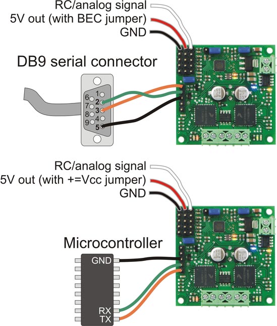 |
TReX Jr RC/serial input signal connections |
|---|
In addition to RC/analog connections, you can connect the TReX Jr to either an RS-232 (COM) or logic-level (TTL) serial port. Note that you should not simultaneously have both RS-232 and TTL connected. The figure above depicts the two possible serial connections. The serial pins are labeled from the perspective of the TReX Jr, meaning you should connect the TReX Jr’s TX or SO line to your target’s receive line (the green wire in the figure above); your TReX Jr’s RX or SI line should connect to your target’s transmit line (the orange wire in the figure above). On a DB9 connector, pin 2 is your computer’s receive line and pin 3 is your computer’s transmit line.
Warning: It is very important that you do not connect your TReX Jr’s TTL pins (SO and SI) to an RS-232 port. RS-232 serial communication signals range from -12 to +12 V, which is well outside the 0 – 5 V expected on those lines. Only the COM pins (TX and RX) are designed to handle RS-232 voltages.
Related products


Home | Forum | Blog | Support | Ordering Information | Lists | Distributors | BIG Order Form | About | Contact
© 2001–2026 Pololu Corporation
