Support » Pololu TReX Jr User’s Guide » 3. Getting Started »
3.a. Motor and Power Connections
The TReX Jr receives its power through the VIN/GND connector terminals. VIN should be between 5 and 24 V and your power source must be able to supply the current your motors will be drawing. The TReX Jr can supply peaks of 5 A and up to a continuous 2.5 A to each of its two bidirectional motors. Performance will depend the on actual system and its ability to dissipate heat. The TReX Jr is designed to help heat flow along the board away from the MC33887 motor driver chips, but addition of a heat sink and good air flow will further improve performance. The TReX Jr can supply up to 10 A (continuous) to the auxiliary motor.
Note: The TReX Jr uses a linear voltage regulator to obtain its logic voltage (5-V Vcc). If you supply a VIN of 24 V, your Vcc line will be limited to a maximum of 50 mA because of the regulator’s 1-W power dissipation rating. This limitation might prevent your TReX Jr from being able to safely power an RC receiver when VIN is so much higher than Vcc.
There are several different ways to connect motors to your TReX Jr:
Option 1:
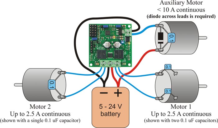 |
TReX Jr motor connections (single battery) |
|---|
The figure above demonstrates how to connect two bidirectional motors and a unidirectional auxiliary motor to your TReX Jr, all powered by the same battery. Note that the auxiliary motor is driven by permanently connecting one lead to power while the board PWMs the other lead between high impedance and ground. You must connect your battery’s ground directly to the upper port of the auxiliary motor’s connection block if you plan to use the auxiliary motor. Otherwise, the auxiliary motor could attempt to pull too much current through the TReX Jr itself, thereby damaging the unit.
The auxiliary motor’s other lead connects to the lower port of its connection block. You will need to connect a diode across the auxiliary motor’s terminals as shown below. Failing to do so will adversely affect the performance of your TReX Jr and could result in permanent damage to the device. Take great care to ensure you do not solder the diode in backwards! You should not solder a diode to your bidirectional motors.
You may find it beneficial to solder 0.1uF capacitors across all of your motors’ terminals. This will decrease the noise put out by your motors and can improve performance of your TReX Jr. You can further decrease the noise put out by your motors by keeping their leads as short as possible and twisting them around each other in a helix.
Option 2:
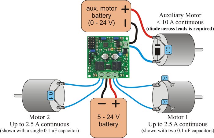 |
TReX Jr motor connections (separate battery for the auxiliary motor) |
|---|
It is possible to power the auxiliary motor with a second, separate 0 – 24 V battery, as shown above. To do so, connect that battery’s ground to the upper of the two auxiliary motor connection block ports. Connect one of your auxiliary motor’s leads to the lower connection block port and connect the other of your motor’s leads directly to the battery’s positive side. You will still need to solder a diode across your auxiliary motor’s terminals.
Option 3:
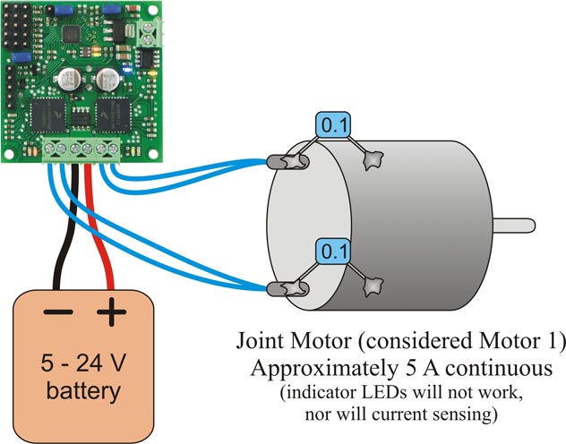 |
TReX Jr joint-motor connection |
|---|
Lastly, you can use both motor 1 and 2 outputs to control a single, more powerful (up to 5 A continuous) bidirectional motor by connecting it as shown above. One of the motor’s terminals connects to both of motor 1’s outputs while the other of the motor’s terminals connects to both of motor 2’s outputs. In order to use your TReX Jr in this way, you must use the serial interface to set the TReX Jr to “joint motor mode”. In this mode, the single bidirectional motor is considered “motor 1”. The motor speed/direction indicator LEDs will not work in this mode, nor will current sensing or channel mixing. Although it is not shown in the figure above, you can additionally control an auxiliary motor while running in “joint motor mode”.
Related products


Home | Forum | Blog | Support | Ordering Information | Lists | Distributors | BIG Order Form | About | Contact
© 2001–2026 Pololu Corporation
