Support »
Sample Project: RC 3pi
View document on multiple pages.
You can also view this document as a printable PDF.
- 1. Introduction
- 2. Materials and Tools
- 3. Construction
- 4. Software
- 5. Suggested Improvements
- 6. Conclusion
1. Introduction
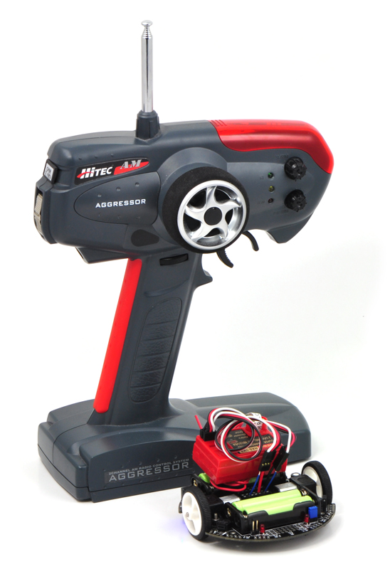 |
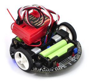
A radio-controlled 3pi with an RC transmitter. |
|---|
The 3pi robot is complete mobile platform designed to excel in line-following and maze-solving competitions. The 3pi has user accessible I/O lines that can be connected to different sensors to expand its behavior beyond line-following and maze-solving. This project shows one possible configuration where a two-channel radio-control (RC) receiver connected to the 3pi enables manual operation of the platform with minimal soldering. Many other sensors could be used to expand the 3pi, including distance sensors to make a wall-following robot.
By connecting an RC receiver and running the program detailed in Section 4, you can turn your 3pi into a radio-controlled vehicle that can drive at speeds in excess of 1 m/s and turn on a dime. A signal mixing algorithm makes two-channel control easy and intuitive, and the 3pi turns off its motors if it goes out of range, starts receiving bad signals, or if the transmitter is turned off. Here is a video of the RC 3pi in action:
2. Materials and Tools
Beyond the Pololu 3pi robot + USB programmer combo, you will need a few other materials for this project. You only need the materials listed under the “required” section to make the RC 3pi work, but the optional header makes it easier to reconfigure your 3pi with other sensors later by allowing you to unplug your RC receiver.
Required
- a two-channel radio-control transmitter/receiver set that outputs standard RC servo pulses
- 2 short female to female servo cables
- 4 wires (such as those from our 140-piece wire kit if you don’t have any wires lying around)
- double-sided foam tape
- a soldering iron and solder
Optional
3. Construction
Connecting the Receiver to the 3pi
Begin by soldering the 2×7 female header where it fits between the 3pi’s gearmotors, as shown in the picture below. If you do not have the header, you can still build an RC 3pi; you will need to solder the wires directly to the 3pi’s circuit board in the places where they would have been inserted into the female header.
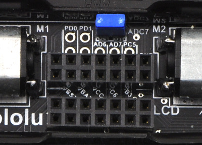 |
A 2×7 female header soldered into the 3pi expansion pin holes. |
|---|
Attach one end of each servo cable to a channel on the RC receiver. Then, with the 3pi turned off, connect the wires as shown in the picture below:
- Connect the signal pin (usually the wire with white or yellow insulation) of one servo cable to PC5 and the signal pin of the other servo cable to PD0. These connections are made with blue wires in the picture below.
- Connect the power pin (usually the wire with red or orange insulation) of one servo cable to VBAT on the 3pi. This will power the receiver directly off of the 3pi’s batteries.
- Connect the ground pin (usually the wire with black or brown insulation) of one servo cable to GND on the 3pi.
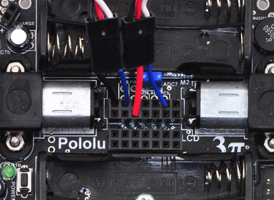 |
The wiring of a radio-controlled 3pi. |
|---|
Remove the PC5 jumper and use double-sided tape to secure the RC receiver and its antenna to the 3pi as shown in the picture below. Note that the receiver might fit better if you first remove the LCD.
 |
A radio-controlled 3pi. |
|---|
Design Considerations and Restrictions
In this project, we used pins PD0 and PC5 because they are available digital inputs. We avoided using PD1 because the LED on that line can pull the signal down and lead to poor performance, depending on how strongly the receiver drives its outputs. ADC6 and ADC7 can only be used as analog inputs and are not ideal for measuring the widths of digital pulses with good accuracy.
Another option is to remove the LCD and use some of those I/O lines to process the signals, though you must be careful not to call any LCD control functions if your receiver channels are connected to pins on the LCD port. If you use pins from the LCD port, you would most likely want to avoid PD7, which has an LED on the line.
Note: Do not use any of the Pololu AVR library’s line sensor functions while your receiver is connected to PC5. Even with the PC5 jumper disconnected, the library’s line sensor routines will attempt to control the emitters by driving PC5 high for the duration of the sensor read and then driving PC5 low. You want PC5 to remain an input for duration of the time it is connected to your receiver. If you want to use the 3pi’s line sensors while your 3pi is under radio control, you will need to modify the library slightly.
4. Software
The final step is to insert fresh batteries into your 3pi and use an AVR ISP programmer (like our USB AVR programmer) to program it with the following code. For information on programming your 3pi, please visit the programming your 3pi section of the 3pi robot user’s guide.
You can download the AVR Studio project with the already compiled hex file here: 3piRC.zip (38k zip)
/**
 * RC 3pi
 *
 * This 3pi robot program reads two standard radio-control (RC) channels and mixes
 * them into motor control. Channel zero (connected to the PD0 input)
 * handles forward and reverse, and channel one (connected to the
 * PC5 input) handles turning.
 *
 */
#include <avr/io.h>
#include <avr/interrupt.h>
#include <pololu/3pi.h>

/**
 * Receiver pulse timings
 *
 * Standard RC receivers output high pulses between 0.5 ms and 2.5 ms with a neutral
 * position of about 1.5 ms. If your RC receiver operates with different pulse
 * widths, change these constants below.
 *
 * The units of these constants is ticks of Timer1 which is set to tick every 3.2
 * microseconds.
 *
 */
const int minPulseTime     = 156;  // 0.5 ms
const int neutralPulseTime = 469;  // 1.5 ms
const int maxPulseTime     = 782;  // 2.5ms
const int maxLowPulseTime  = 3000; // 9.6ms

struct ChannelStruct
{
	volatile unsigned int prevTime;
	volatile unsigned int lowDur;
	volatile unsigned int highDur;
	volatile unsigned char newPulse;

	unsigned int pulse;
	unsigned char error;
};

struct ChannelStruct ch[2];

/*
 * Pin Change interrupts
 * PCI0 triggers on PCINT7..0
 * PCI1 triggers on PCINT14..8
 * PCI2 triggers on PCINT23..16
 * PCMSK2, PCMSK1, PCMSK0 registers control which pins contribute.
 *
 * The following table is useful:
 *
 * AVR pin    PCINT #            PCI #
 * ---------  -----------------  -----
 * PB0 - PB5  PCINT0 - PCINT5    PCI0
 * PC0 - PC5  PCINT8 - PCINT13   PCI1
 * PD0 - PD7  PCINT16 - PCINT23  PCI2
 *
 */

// This interrupt service routine is for the channel connected to PD0
ISR(PCINT2_vect)
{
	// Save a snapshot of PIND at the current time
	unsigned char pind = PIND;
	unsigned int time = TCNT1;

	if (pind & (1 << PORTD0))
	{
		// PD0 has changed to high so record the low pulse's duration
		ch[0].lowDur = time - ch[0].prevTime;
	}
	else
	{
		// PD0 has changed to low so record the high pulse's duration
		ch[0].highDur = time - ch[0].prevTime;
		ch[0].newPulse = 1; // The high pulse just finished so we can process it now
	}
	ch[0].prevTime = time;
}

// This interrupt service routine is for the channel connected to PC5
ISR(PCINT1_vect)
{
	// Save a snapshot of PINC at the current time
	unsigned char pinc = PINC;
	unsigned int time = TCNT1;

	if (pinc & (1 << PORTC5))
	{
		// PC5 has changed to high so record the low pulse's duration
		ch[1].lowDur = time - ch[1].prevTime;
	}
	else
	{
		// PC5 has changed to low so record the high pulse's duration
		ch[1].highDur = time - ch[1].prevTime;
		ch[1].newPulse = 1; // The high pulse just finished so we can process it now
	}
	ch[1].prevTime = time;
}


/**
 * updateChannels ensures the recevied signals are valid, and if they are valid
 * it stores the most recent high pulse for each channel.
 */
void updateChannels()
{
	unsigned char i;

	for (i = 0; i < 2; i++)
	{
		cli(); // Disable interrupts
		if (TCNT1 - ch[i].prevTime > 35000)
		{
			// The pulse is too long (longer than 112 ms); register an error
			// before it causes possible problems.
			ch[i].error = 5; // wait for 5 good pulses before trusting the signal

		}
		sei(); // Enable interrupts

		if (ch[i].newPulse)
		{
			cli(); // Disable interrupts while reading highDur and lowDur
			ch[i].newPulse = 0;
			unsigned int highDuration = ch[i].highDur;
			unsigned int lowDuration = ch[i].lowDur;
			sei(); // Enable interrupts

			ch[i].pulse = 0;

			if (lowDuration < maxLowPulseTime ||
				highDuration < minPulseTime ||
				highDuration > maxPulseTime)
			{
				// The low pulse was too short or the high pulse was too long or too short
				ch[i].error = 5; // Wait for 5 good pulses before trusting the signal
			}
			else
			{
				// Wait for error number of good pulses
				if (ch[i].error)
					ch[i].error--;
				else
				{
					// Save the duration of the high pulse for use in the channel mixing
					// calculation below
					ch[i].pulse = highDuration;
				}
			}
		}
	}
}


int main()
{
	ch[0].error = 5; // Wait for 5 good pulses before trusting the signal
	ch[1].error = 5;

	DDRD &= ~(1 << PORTD0);	// Set pin PD0 as an input
	PORTD |= 1 << PORTD0;	// Enable pull-up on pin PD0 so that it isn't floating
	DDRC &= ~(1 << PORTC5); // Set pin PC5 as an input
	PORTC |= 1 << PORTC5;	// Enable pull-up on pin PC5 so that it isn't floating
	delay_ms(1);			// Give the pull-up voltage time to rise

	PCMSK1 = (1 << PORTC5);	// Set pin-change interrupt mask for pin PC5
	PCMSK2 = (1 << PORTD0);	// Set pin-change interrupt mask for pin PD0
	PCIFR = 0xFF;			// Clear all pin-change interrupt flags
	PCICR = 0x06;			// Enable pin-change interrupt for masked pins of PORTD
							//  and PORTC; disable pin-change interrupts for PORTB
	sei();					// Interrupts are off by default so enable them

	TCCR1B = 0x03;	// Timer 1 ticks at 20MHz/64 = 312.5kHz (1 tick per 3.2us)

	while (1) // Loop forever
	{
		updateChannels();

		// Every 100 ms display the pulse timings on the LCD
		// this is good for debugging your RC 3pi but not necessary if
		// you remove the LCD
		if (get_ms() % 100 == 0)
		{
			lcd_goto_xy(0, 0);
			print("ch1 ");
			// Multiplying by 32/10 converts ticks to microseconds
			print_unsigned_long(ch[0].pulse * 32 / 10);
			print("    ");
			lcd_goto_xy(0, 1);
			print("ch2 ");
			print_unsigned_long(ch[1].pulse * 32 / 10);
		}

		if (ch[0].error || ch[1].error)
		{
			// If either channel is not getting a good signal, stop
			set_motors(0, 0);
		}
		else
		{
			/**
			 * Mix calculation
			 *
			 * This calculation mixes the pulses from the two channels
			 * to make control intuitive. Channel 0 controls foward and
			 * reverse. When the pulse is longer than neutralPulseTime it
			 * adds to m1 and m2; when the pulse is shorter than nuetralPulseTime
			 * it subtracts from m1 and m2. Channel 1 controls rotation. When the
			 * pulse is longer than neutralPulseTime it subtracts from m1 and adds
			 * to m2; when the pulse is shorter than neutralPulseTime it adds to m1
			 * and subtracts from m2. m1 and m2 are then scaled so they fit within
			 * -255 to 255 range.
			 *
			 * Calibration
			 *
			 * Your transmitter/receiver might treat channels 0 and 1 differently
			 * than the receiver this code was developed for. If your 3pi turns
			 * when you expect it to go straight or vice versa, you may need to flip
			 * a sign in the calculation below or swap the connections at the receiver.
			 *
			 */
			long m1 = (neutralPulseTime - (int)ch[0].pulse) +
                      ((int)ch[1].pulse - neutralPulseTime);
			long m2 = (neutralPulseTime - (int)ch[0].pulse) -
                      ((int)ch[1].pulse - neutralPulseTime);
			m1 = m1 * 255 / minPulseTime;
			m2 = m2 * 255 / minPulseTime;
			set_motors(m1, m2);
		}
	}

    // This part of the code is never reached.  A robot should
    // never reach the end of its program, or unpredictable behavior
    // will result as random code starts getting executed.  If you
    // really want to stop all actions at some point, set your motors
    // to 0,0 and run the following command to loop forever:
    //
	// set_motors(0,0);
    // while(1);
}
Please note that individual transmitter/receiver systems vary, so you might need to modify this code some before it will work well with your particular system. If you run the program with the LCD connected, it will report back the duration of the pulses it’s detecting on each channel in microseconds. You can then use the trim settings on your transmitter to adjust the neutral points to 1.5 ms, or you can modify the neutral points in the code. You also might want to characterize the ranges of the pulses and adjust the motor speed scaling so that the motors reach full speed when the transmitter sticks are at their full extents. Lastly, you might need to change some of the signs in the channel mixing formulas so that the robot responds intuitively (e.g. so that it turns left rather than right when you move the stick left).
5. Suggested Improvements
- Program the 3pi to automatically measure the neutral, maximum, and minimum value of each channel so that responds better to the transmitter. Doing this will ensure that the robot is at a full stop when the transmitter sticks are in their neutral positions and that the motors reach full speed appropriately when the sticks are at the ends of their ranges.
- Program the 3pi to drive autonomously when the transmitter is off and drive under your control while the transmitter is on. This would let you use the RC system as an emergency manual override.
- Use the RC system to control parameters of an autonomous program, such as the maximum speed of a line follower or the direction a maze solver should go at the next intersection.
- Use a transmitter/receiver with more channels to give you control over more 3pi functions. You could connect these extra channels to LCD-port I/O lines and use them to trigger additional actions such as playing sounds with the buzzer. The easiest way to add a third channel would be via a PORTB pin, since you could use pin-change interrupt 0 to read the pulses just like pin-change interrupt 1 reads the pulses on PC5 and pin-change interrupt 2 reads the pulses on PD0. If you try to use two pins on the same port to read separate channels, the required changes to the code become more complicated.
6. Conclusion
With the addition of an RC receiver and some simple code, the 3pi can become a radio-controlled robot with a nice speed and excellent turning ability. We encourage you to try to improve upon this project by adding more sensors or even by merely enhancing the code.
Please join us on our robotics forum to ask questions, give feedback, or share your 3pi projects. We would love to hear about your experiences implementing this project on your own 3pi, and we would be delighted to see any improvements or alterations you make!
Related products


Home | Forum | Blog | Support | Ordering Information | Lists | Distributors | BIG Order Form | About | Contact
© 2001–2026 Pololu Corporation
