Support » Pololu USB AVR Programmer User’s Guide » 1. Overview »
1.a. Module Pinout and Components
 |
Pololu USB AVR programmer, labeled top view. |
|---|
The Pololu USB AVR programmer connects to a computer’s USB port via an included USB A to mini-B cable, and it connects to the target device via an included 6-pin ISP programming cable (the older, 10-pin ISP connections are not directly supported, but it is easy to create or purchase a 6-pin-to-10-pin ISP adapter).
The USB AVR programmer has three indicator LEDs:
- The green LED indicates the USB status of the device. When you connect the programmer to the computer via the USB cable, the green LED will start blinking slowly. The blinking continues until it receives a particular message from the computer indicating that the drivers are installed correctly. After the programmer gets this message, the green LED will be on, but it will flicker briefly when there is USB activity.
- The yellow LED indicates that the programmer is doing something. When it is blinking, it means that the programmer has detected the target device (the voltage on the target VDD line is high). When it is on solid, it means that the SLO-scope is enabled, and lines A and B are used for the SLO-scope instead of the USB-to-TTL-serial adapter.
- The red LED indicates an error or warning. When it is blinking, it means that the target device is not detected (the voltage on the target VDD line is low). When it is on solid, it means that the last attempt at programming resulted in an error. You can determine the source of the error by running the configuration utility (see Section 3.e).
The VBUS line provides direct access to the 5V VBUS line on the USB cable and can be used to power additional devices. The line can provide up to 100 mA, so the current draw of your programmer plus any additional devices should not exceed this amount. If you attempt to draw more than this limit, your computer might disconnect the USB port temporarily or take other actions to limit the use of USB power.
The GND line provides direct access to the grounded line on the USB cable (and ground on the programmer).
The TX and RX lines are the TTL serial port for the USB-to-TTL-serial adapter. They are labeled from the computer’s perspective: TX is an output that connects to your target’s serial receive pin and RX is an input that connects to your target’s serial transmit pin. Section 6 describes how to use these lines to communicate with your devices from the computer.
The A and B lines can be used as serial control/handshaking lines for the USB-to-TTL-serial adapter (see Section 6.a) or as analog voltage inputs for the SLO-scope (see Section 7).
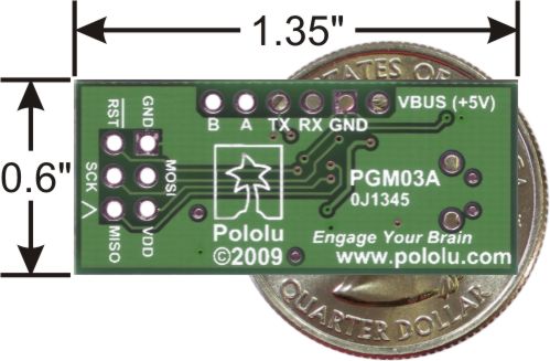 |
Pololu USB AVR programmer bottom view with dimensions. |
|---|
The USB AVR programmer has a standard 6-pin AVR ISP connector for programming AVRs, and the pins are labeled on the silkscreen on the bottom side of the board. The pins on the connector are:
- MISO: The “Master Input, Slave Output” line for SPI communication with the target AVR. The programmer is the master, so this line is an input.
- VDD: An input line that the programmer uses to measure the voltage of the target AVR. While programming the target device, the programmer uses this line to constantly monitor the target VDD. If the voltage goes too low or varies too much, then the programmer aborts programming in order to avoid damage to the target AVR. Section 3.e has more information about target VDD monitoring. The VDD line is not used to power the programmer; the programmer is powered from the USB. This line cannot be used to power the target device; the target device must be independently powered for programming to work.
- SCK: The clock line for SPI communication with the target AVR. The programmer is the master, so this line is an output during programming.
- MOSI: The “Master Output, Slave Input” line for SPI communication with the target AVR. The programmer is the master, so this line is an output during programming.
- RST: The target AVR’s reset line. This line is used as an output driven low during programming to hold the AVR in reset.
- GND: Ground. This line should be connected to the target device’s ground.


Home | Forum | Blog | Support | Ordering Information | Lists | Distributors | BIG Order Form | About | Contact
© 2001–2026 Pololu Corporation
