Support » Pololu USB AVR Programmer User’s Guide » 3. Getting Started in Windows »
3.e. Configuring the Programmer
The Pololu USB AVR programmer can be configured using the Pololu USB AVR Programmer Configuration Utility for Windows. The utility comes with the Windows drivers (Section 3.a). You can run it from your Start Menu, or by just double clicking on the executable pgm03a_config.exe. This section describes all the available settings and what they do.
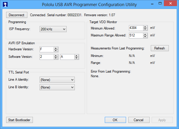 |
Pololu USB AVR programmer configuration utility for Windows. |
|---|
Target VDD Monitor
The USB AVR programmer monitors the voltage of the target AVR while it is being programmed to ensure that ISP commands are only sent when the AVR’s VDD is at a safe level, since attempting to program an underpowered AVR can permanently disable it. There are two parameters that control this feature:
- Minimum Allowed: This parameter determines the lowest level (in millivolts) that the target AVR’s VDD is allowed to go. If the target AVR’s VDD drops below this level, the programmer immediately aborts programming and turns on the red programming LED. Lowering this value will allow programming of AVRs at lower voltages, but will make it more likely that the programmer will send ISP commands to the AVR while the AVR is running at an unsafe voltage. The default value is 4384 mV.
- Maximum Range Allowed: This parameter determines how much the target AVR’s VDD measurements are allowed to vary (in millivolts). When the programmer recieves an ISP programming request, it starts keeping track of the maximum and minimum measurements of the AVR’s VDD. If the difference between the maximum and minimum exceeds the allowed maximum range, the programmer immediately aborts programming and turns on the red programming LED. Increasing this value will allow programming of AVRs under less stable power conditions, but will make it more likely that the programmer will send ISP commands to the AVR while the AVR is running at an unsafe voltage. The default value is 512 mV.
Measurements From Last Programming
This section displays the minimum and range of the target VDD measurements from the last time the programmer was in programming mode or tried to enter programming mode. This can help determine whether programming problems are due to the target’s power supply.
Error From Last Programming
When an error or unexpected condition causes the programmer to leave programming mode, or fail to enter programming mode, then the programmer turns on the red LED and records the error code. A description of the error can be found here. See Troubleshooting (Section 8) for details on specific error messages.
ISP Frequency
The higher the ISP frequency, the faster you can program the target AVR, but the ISP frequency must be less than a quarter of the target AVR’s clock frequency.
The ISP frequency can be set in Atmel Studio (see Section 3.b.2) as well as in the Configuration Utility, but the frequencies listed in the Atmel Studio user interface do not match the actual frequencies used by the Pololu USB AVR programmer. The correspondence is shown below:
| Frequency Listed in Atmel Studio |
Actual Frequency | Allowed Target Frequency |
|---|---|---|
| 1.843 MHz | 2000 kHz | > 8 MHz |
| 460.8 kHz | 1500 kHz | > 6 MHz |
| 115.2 kHz | 750 kHz | > 3 MHz |
| 57.6 kHz | 200 kHz | > 800 kHz |
| 28.36 kHz | 4.0 kHz | > 16 kHz |
| 14.07 kHz | ||
| 7.009 kHz | 1.5 kHz* | > 6 kHz |
| 4.00 kHz | ||
| 3.498 kHz | ||
| 1.748 kHz | ||
| 1.21 kHz |
An AVR running at 20 MHz or higher (e.g. the Orangutan SV-xx8, Orangutan LV-168, Baby Orangutan, and 3pi robot) can be programmed at 2000 kHz (1.845 MHz in Atmel Studio), which is the fastest setting.
An AVR running at 8 MHz or higher (e.g. the original Orangutan) can be programmed at 1500 kHz (460.8 kHz in AVR Studio).
An AVR running at 1 MHz, such as one clocked off of the internal RC oscillator with the divide-by-8 fuse bit programmed, can be programmed at an ISP frequency as high as 200 kHz (57.6 kHz in Atmel Studio). This is the USB AVR programmer’s default ISP frequency.
The two lowest frequencies support AVRs with a clock frequency under 1 MHz. The 1.5 kHz setting is too slow to actually program the flash or EEPROM on your target device using Atmel Studio (it will timeout while attempting to program the flash/EEPROM pages), but it will still let you set the fuses. Be aware that if you attempt to program flash or EEPROM at 4.0 kHz, it might take five minutes or longer to program a 16KB of flash, so we only recommend this ISP frequency for putting small programs on very low-frequency AVRs.
Serial Number
This is a unique identifier assigned to this programmer by Pololu. This number can not be changed.
TTL Serial Port
This section is used to identify pins A and B with serial handshaking lines so that they can be used as general purpose user I/O lines. See Section 6.a.
AVR ISP Emulation
This section is used to change the hardware and software version numbers of the programmer. These numbers are read by Atmel Studio when it connects to the programmer and are expressed in hex. If these numbers do not match the numbers that Atmel Studio expects, then it might bring up a dialog asking if you want to upgrade (or downgrade) your programmer’s firmware; the Pololu AVR USB programmer does not support this method of firmware upgrading, so this dialog is nothing more than a nuisance to those not using an Atmel programmer. You should click Cancel to ignore the message and proceed to the AVRISP programming dialog. To prevent this firmware-upgrade dialog from appearing in the future, set the numbers here to the numbers that AVR Studio says it expects.


Home | Forum | Blog | Support | Ordering Information | Lists | Distributors | BIG Order Form | About | Contact
© 2001–2026 Pololu Corporation
