Support » Pololu Orangutan SV-xx8 and LV-xx8 User’s Guide »
4. Module Pinouts, Component Identification, and Usage Notes
Components
|
|
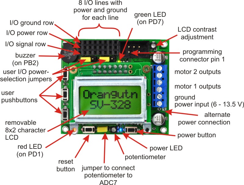

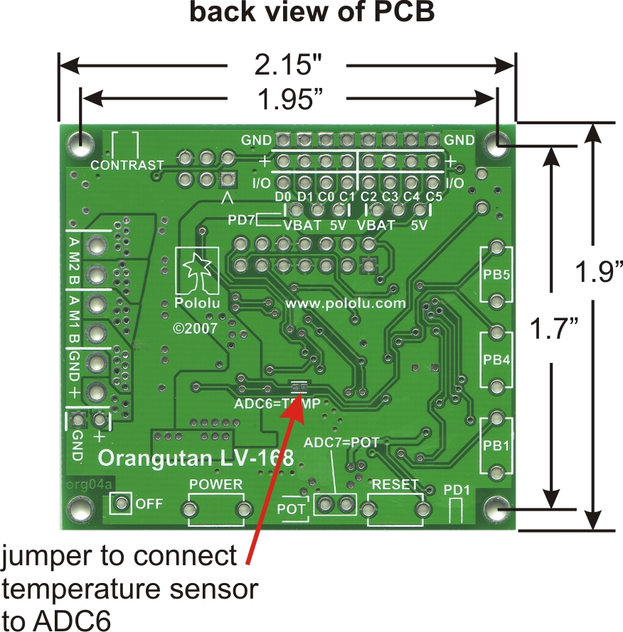
The Orangutan contains a programmable ATmega168 or ATmega328P AVR microcontroller, a dual motor driver for direct control of two DC motors, an 8×2 character LCD, a buzzer, three user pushbuttons, two user LEDs, and a 10k user trimmer potentiometer. These and the rest of the main features of the Orangutan modules are labeled in the pictures above. Most of the connections points are also indicated on the silkscreen on the back side of the PCB, as shown below. The overall unit dimensions are 2.15" x 1.9", and four 0.086" mounting holes, suitable for #2 screws, are located 0.1" from the corners of the board (the top-left mounting hole is usually obscured by the buzzer).
|
|

Orangutan SV-xx8 Power & Motor Connections
The power and motor connections are on the right side of the unit. The Orangutan SV-xx8’s input voltage should be 6 – 13.5 V, from which the on-board regulator generates the 5 V that is used to power the logic. In its factory configuration, analog input ADC6 is connected through a jumper to a third of the battery voltage so that you can monitor the state of your batteries.
The Orangutan SV-xx8’s TB6612FNG motor driver can deliver a continuous 1 A per motor channel, and can briefly deliver up to 3 A per motor channel. If you aren’t taking extra steps to keep the motor driver cool, such as using a heat sink, exceeding this continuous current rating for too long will cause the motor driver to heat up and trigger its built-in thermal shutdown.
Orangutan LV-168 Power & Motor Connections
Just like the Orangutan SV-xx8, the power and motor connections are on the right side of the unit. The Orangutan LV-168 is designed to operate off of three NiMH cells, which corresponds to a voltage range of about 2.5 – 4.5 V. However, the unit can operate from two or four NiMH cells with some limitations. At lower voltages, the effectiveness of the motor drivers (H-bridges) is reduced, and the 5 V step-up regulator’s available output current decreases. Beyond 5 V, the step-up regulator ceases operation and the input voltage shows up on the Vcc line; the components on the board can operate to 5.5 V, but some sensors you use might have a 5.25 V limit.
The Orangutan LV-168’s motor drivers can briefly deliver up to 5 A each, but each motor driver is protected by a 2 A resettable fuse that is triggered by excessive temperature. If the motors draw much more than 2 A for more than a few seconds, the voltage to the motors will be reduced, but normal operation will resume once the board has cooled down. In its factory configuration, an on-board temperature sensor is connected through a jumper to ADC6 for some (limited) feedback about the board temperature.
User I/O & Power Outputs
The eight user I/O lines can be accessed via the 8×3 0.100" female header along the upper edge of the board, as shown below. Each line has associated power and ground connections for easy connections to sensors: the exterior (top) pin is ground, the middle pin is power, and the interior(bottom) pin is signal and connects directly to an AVR I/O line.
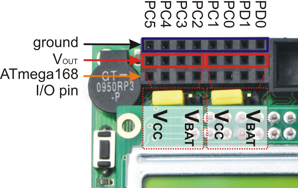 |
Orangutan SV-xx8 and LV-168 user I/O header. |
|---|
The power row is divided into two banks of four pins, and each bank can either connect directly to the battery voltage or to the 5 V generated on the board; this connection is determined by the bank’s associated power selection jumper. On the Orangutan LV-168, the total current available to the 5 V line is approximately 150 mA, but the exact amount depends on your input voltage. On the Orangutan SV-xx8, the total current available to the 5 V line is 3 A, meaning you can power servos and other high-power peripherals directly from your regulated voltage. Please note that you should use something more robust than the supplied power-selection shorting blocks if you plan on pulling much more than an amp from a single bank.
From left to right, the signal connections along the bottom row are: PC5, PC4, PC3, PC2, PC1, PC0, PD1, and PD0. Pins PC0 – PC5 can be used as either digital I/Os or analog inputs. Pins PD0 and PD1 are digital I/Os that connect to the ATmega168’s UART hardware, which means you can use them as logic-level (TTL) serial receive and transmit lines, respectively. Two additional dedicated analog inputs (ADC6 and ADC7) are connected by default to hardware on the board, but their jumpers can be removed to provide user access to these inputs. ADC7 is connected to the user trimmer potentiometer by the shorting block next to the reset button; the left pin of the shorting block header is tied directly to ADC7. ADC6 is connected to the LV-168’s temperature sensor and the SV-xx8’s battery voltage monitoring circuit via a surface-mount jumper on the bottom side of the PCB. You can use a soldering iron to break this short, and you can make your own connection to ADC6 using the right of the two shorting pads.
Motors
The motor drivers are controlled by the AVRs hardware PWM outputs on eight-bit timers 0 and 2, which lets you achieve variable motor speeds using hardware rather than processor-intensive software PWMs on the motor control lines. The two Timer0 PWM outputs connect to both of motor 1’s direction inputs and the two Timer2 PWM outputs connect to both of motor 2’s direction inputs. Note that one of the motor control pins (PB3) is also used during programming as a SPI line (MOSI), which this means that you cannot use SPI on the Orangutan without unintentionally driving one of the motors. Programming the Orangutan does not drive the motors because the motor driver circuitry is disabled while the board is reset.
LCD
The Orangutan is supplied with a removable 8×2 character LCD that uses the common HD44780 parallel interface (109k pdf); a larger display can be connected instead with an appropriate cable. The ATmegaxx8 has four I/O lines connected to LCD data lines DB4 – DB7 (i.e. is configured to use the LCD in 4-bit mode) and three I/O lines connected to the three LCD control lines RS, R/W, and E. Please see the schematic for more information. Please note that the LCD data lines are also shared by the user pushbuttons, the green user LED, and the programming connector.
Pushbuttons
The Orangutan has five total pushbuttons: a power on/off button located on the right side of the bottom edge of the board, a reset button located on the left side of the bottom edge of the board, and three user pushbuttons along the left edge of the board. Please note that the power button turns off power to the entire board, and the reset button connects directly to the ATmegaxx8’s reset pin. The user buttons, from top to bottom, are on pins PB5, PB4, and PB1. Pressing one of these user pushbuttons pulls the associated I/O pin to ground through a 1kΩ resistor, so to use the buttons you should configure them as inputs with their internal pull-up resistors enabled. Note that pushbuttons physically bounce when pressed, so make sure you take this phenomenon into account when writing your button-handling code. Additionally, since the LCD and pushbuttons share I/O lines, the LCD lines must be in high-impedance mode (i.e. both the AVR and the LCD should not be trying to write to the lines) for you to be able to read the pushbuttons.
Note: The user pushbuttons lines are shared by the programming connector, so you should not press the user pushbuttons while your Orangutan is being programmed.
Buzzer
The buzzer is on pin PB2, which can be used as a normal digital I/O or configured as a hardware PWM output driven by the ATmegaxx8’s 16-bit Timer1. If you alternate between driving the buzzer pin high and low at a given frequency, the buzzer will produce sound at that frequency. By taking advantage of the hardware PWM output on the buzzer pin, you can have the buzzer playing in the background while the rest of your program executes. Please see the buzzer section of the Pololu AVR library for more information.
LEDs
The Orangutan comes with a blue power LED (located next to the power button) and two user LEDs: one red and one green. The red user LED is located next to the reset button and is on the user I/O line PD1; it will light if you set PD1 as a high output. The green user LED is located between the user I/O header and the LCD and is connected to pin PD7; it will light if you set PD7 as a high output. Note that PD7 is also used as an LCD data line, so you will see the green LED flicker when you update the LCD.
Programming Connector
The Orangutan has a 6-pin programming connector on the upper right side; the robot controller is designed for an AVR ISP in-system programmer from Atmel or a compatible programmer, such as the Pololu Orangutan USB programmer. Pin 1 is the pin most toward the inside of the board.
Related products


Home | Forum | Blog | Support | Ordering Information | Lists | Distributors | BIG Order Form | About | Contact
© 2001–2026 Pololu Corporation
