Support »
Arduino Library for the Pololu QTR Reflectance Sensors
View document on multiple pages.
You can also view this document as a printable PDF.
1. Introduction
This guide is for an older version of the QTRSensors Arduino library (3.1.0). The current version of the library can be found on GitHub, and its documentation is here.
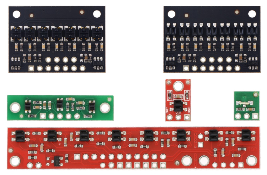 |
QTR sensor size comparison. Top row: QTRX-HD-07, QTR-HD-07; middle row: QTR-3, QTR-1, QTR-L-1; bottom row: QTR-8. |
|---|
The Pololu QTR reflectance sensors carry infrared LED and phototransistor pairs that can provide analog measurements of IR reflectance, which makes them great for close-proximity edge detection and line-following applications. The modules come as compact, single-sensor units (QTR-1A and QTR-1RC; QTR-L-1A and QTR-L-1RC), 3-sensor arrays (QTR-3A and QTR-3RC), or as 8-sensor arrays (QTR-8A and QTR-8RC) that can be optionally split into a 2-sensor array and a 6-sensor array.
The modules are available in two different output formats: the QTR-xA outputs an analog voltage between 0 and Vcc that can be measured by an analog-to-digital converter (ADC), and the QTR-xRC outputs require a digital I/O line capable of driving the output line high and then measuring the time for the output voltage to decay (which provides an analog measurement of reflectance).
|
|

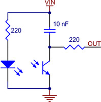 |
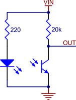
QTR-1RC and QTR-L-1RC reflectance sensor schematic diagram. |
|---|
Please see the product pages for more information on how these sensors work.
This document will explain how to install Arduino libraries for the Pololu QTR reflectance sensors, and it will provide sample sketches as well as links to library documentation. The libraries will give you everything you need to interface with a QTR-8x reflectance sensor array or multiple QTR-1x reflectance sensors, including advanced features like automatic calibration and, in the case of line detection, calculation of the line’s position.
2. Library Installation
If you are using version 1.6.2 or later of the Arduino software, you can use the Library Manager to install this library:
In the Arduino IDE, open the “Sketch” menu, select “Include Library”, then “Manage Libraries…”.
- Search for “QTRSensors”.
- Click the QTRSensors entry in the list.
- Click “Install”.
If this does not work, you can manually install the library:
- Download the latest release archive from GitHub and decompress it.
- Rename the folder “qtr-sensors-arduino-xxxx” to “QTRSensors”.
- Drag the “QTRSensors” folder into the “libraries” directory inside your Arduino sketchbook directory. You can view your sketchbook location by opening the “File” menu and selecting “Preferences” in the Arduino IDE. If there is not already a “libraries” folder in that location, you should make the folder yourself.
- After installing the library, restart the Arduino IDE.
You should now be able to use these libraries in your sketches by selecting Sketch > Import Library > QTRSensors from your Arduino IDE (or simply type #include <QTRSensors.h> at the top of your sketch). Note that you might need to restart your Arduino IDE before it sees the new libraries.
Once this is done, you can create a QTRSensorsAnalog object for your QTR-xA sensors and a QTRSensorsRC object for your QTR-xRC sensors:
// create an object for three QTR-xA sensors on analog inputs 0, 2, and 6
QTRSensorsAnalog qtra((unsigned char[]) {0, 2, 6}, 3);

// create an object for four QTR-xRC sensors on digital pins 0 and 9, and on analog
// inputs 1 and 3 (which are being used as digital inputs 15 and 17 in this case)
QTRSensorsRC qtrrc((unsigned char[]) {0, 9, 15, 17}, 4);
This library takes care of the differences between the QTR-xA and QTR-xRC sensors internally, providing you with a common interface to both sensors. The only external difference is in the constructors, as you can see in the code sample above. The first argument to the QTRSensorsAnalog constructor is an array of analog input pins (0 – 7) while the first argument to the QTRSensorsRC constructor is an array of digital pins (0 – 19). Note that analog inputs 0 – 5 can be used as digital pins 14 – 19. For more details, see Section 3.
The only other difference you might experience is in the time it takes to read the sensor values. The QTR-xRC sensors can all be read in parallel, but each requires the timing of a pulse that might take as long as 3 ms (you can specify how long the library should time this pulse before timing out and declaring the result full black). The QTR-xA sensors use the analog-to-digital converter (ADC) and hence must be read sequentially. Additionally, the analog results are produced by internally averaging a number of samples for each sensor (you can specify the number of samples to average) to decrease the effect of noise on the results.
Several example sketches are available to help you get started. To view the example sketches, open the Arduino IDE and navigate to:
File > Examples > QTRSensors
As a first step, we recommend using QTRARawValuesExample (for QTR-xA sensors) or QTRRCRawValuesExample (for the QTR-xRC sensors). These examples will simply print the raw readings from the sensors to the serial monitor, using 9600 baud. Once that is working, you might want to try one of the more advanced examples, QTRAExample or QTRRCExample, which incorporate calibration and also estimate the position of a line.
3. QTRSensors Methods & Usage Notes
QTRSensors Command Reference
Previous versions of this library were named PololuQTRSensors, but we have changed it to QTRSensors to differentiate it from the QTR sensor library in our Arduino Libraries for the Orangutan and 3pi Robot.
This documentation is for version 3.1.0 of the QTRSensors library. Older versions of the library do not support the dimmable QTR and QTRX sensors.
This library defines a class for each of the QTR sensor types, and it takes care of the differences between the analog and RC sensors internally, providing you with a common interface to all types.
For non-dimmable QTR-xA sensors, you will want to instantiate a QTRSensorsAnalog object, and for non-dimmable QTR-xRC sensors. you will want to instantiate a QTRSensorsRC object. Aside from the constructors, these two objects provide the same methods for reading sensor values (both classes are derived from the same abstract base class). The library provides access to the raw sensors values as well as to high level functions including calibration and line-tracking.
For dimmable QTR-xD-xA and QTRX-xD-xA sensors, you will want to instantiate a QTRDimmableAnalog object, and for dimmable QTR-xD-xRC and QTRX-xD-xRC sensors. you will want to instantiate a QTRDimmableRC object. These classes support changing the emitter dimming levels and controlling the odd and even emitters separately on the dimmable sensors.
Each of these classes must be instantiated before they are used. This allows multiple QTR sensor arrays to be controlled independently as separate objects.
For calibration, memory is allocated using the malloc() command. This conserves RAM: if eight sensors are calibrated with the emitters both on an off, a total of 64 bytes would be dedicated to storing calibration values. However, for an application where only three sensors are used, and the emitters are always on during reads, only 6 bytes are required.
Internally, this library uses all standard Arduino functions such as micros() for timing and analogRead() or digitalRead() for getting the sensor values, so it should work on all Arduinos without conflicting with other libraries.
void read(unsigned int *sensorValues, unsigned char readMode = QTR_EMITTERS_ON)
Reads the raw sensor values into an array. There MUST be space for as many values as there were sensors specified in the constructor. The values returned are a measure of the reflectance in units that depend on the type of sensor being used, with higher values corresponding to lower reflectance (a black surface or a void). QTR-xA sensors will return a raw value between 0 and 1023. QTR-xRC sensors will return a raw value between 0 and the timeout argument (in units of microseconds) provided in the constructor (which defaults to 2500).
The functions that read values from the sensors all take an argument readMode, which specifies the kind of read that will be performed. Several options are defined: QTR_EMITTERS_OFF specifies that the reading should be made without turning on the infrared (IR) emitters, in which case the reading represents ambient light levels near the sensor; QTR_EMITTERS_ON specifies that the emitters should be turned on for the reading, which results in a measure of reflectance; and QTR_EMITTERS_ON_AND_OFF specifies that a reading should be made in both the on and off states. The values returned when the QTR_EMITTERS_ON_AND_OFF option is used are given by on + max – off, where on is the reading with the emitters on, off is the reading with the emitters off, and max is the maximum sensor reading. This option can reduce the amount of interference from uneven ambient lighting. Note that emitter control will only work if you specify a valid emitter pin in the constructor.
Dimmable QTR sensors with separate CTRL ODD and CTRL EVEN pins also support QTR_EMITTERS_ODD_EVEN, where first the odd sensors are read with only the odd emitters on, then the even sensors are read with only the even emitters on, as well as QTR_EMITTERS_ODD_EVEN_AND_OFF, which works like a combination of ODD_EVEN and ON_AND_OFF: the odd sensors are read with the odd emitters on, the even sensors are read with the even emitters off, and all sensors are read with all emitters off. These two modes only work if you specify separate odd and even emitter control pins in the constructor.
Alternatively, any QTR sensor can be read with QTR_EMITTERS_MANUAL instead. This causes the read method to leave the emitters in their existing states instead of automatically turning them on or off before and after each reading.
Example usage:
unsigned int sensor_values[8];
sensors.read(sensor_values);
void emittersOn()
Turn the IR LEDs on. This is mainly for use by the read method, and calling these functions before or after the reading the sensors will have no effect on the readings unless readMode is QTR_EMITTERS_MANUAL, but you may wish to use these for testing purposes. This method will only do something if the emitter pin specified in the constructor is not QTR_NO_EMITTER_PIN.
void emittersOn(unsigned char bank, bool wait = true)
Dimmable only: This version of emittersOn() turns on the emitters for the specified bank, which is either QTR_BANK_ODD or QTR_BANK_EVEN. It will only work if you have specified separate odd and even emitter pins. If wait is false, the function will return immediately instead of waiting until the emitters actually turn on.
void emittersOff()
Turn the IR LEDs off. This is mainly for use by the read method, and calling these functions before or after the reading the sensors will have no effect on the readings unless the readMode is QTR_EMITTERS_MANUAL, but you may wish to use these for testing purposes.
void emittersOff(unsigned char bank, bool wait = true)
Dimmable only: This version of emittersOff() turns off the emitters for the specified bank, which is either QTR_BANK_ODD or QTR_BANK_EVEN. It will only work if you have specified separate odd and even emitter pins. If wait is false, the function will return immediately instead of waiting until the emitters actually turn off.
void emitterBankSelect(unsigned char bank)
Dimmable only: This function turns on the selected bank (QTR_BANK_ODD or QTR_BANK_EVEN) of emitters while turning off the other bank. It performs both of these operations at the same time and waits for both banks of emitters to be in the right states before returning, but it eliminates unnecessary delays that would happen if you called emitersOff() and emittersOn() separately. This function will only work if you have specified separate odd and even emitter pins.
void setDimmingLevel(unsigned char dimmingLevel)
Dimmable only: Sets the dimming level for the emitters (0–31). A dimming level of 0 corresponds to full current and brightness, with higher dimming levels meaning lower currents; see your sensor board’s product page for details. The dimming level takes effect the next time emittersOn() is called (which can happen in the read method). If the emitters are already on, you should call emittersOff() before calling emittersOn() to apply the dimming level.
unsigned char getDimmingLevel()
Dimmable only: Returns the current emitter dimming level.
void calibrate(unsigned char readMode = QTR_EMITTERS_ON)
Reads the sensors for calibration. The sensor values are not returned; instead, the maximum and minimum values found over time are stored internally and used for the readCalibrated() method. You can access the calibration (i.e raw max and min sensor readings) through the public member pointers calibratedMinimumOn, calibratedMaximumOn, calibratedMinimumOff, and calibratedMaximumOff. Note that these pointers will point to arrays of length numSensors, as specified in the constructor, and they will only be allocated after calibrate() has been called. If you only calibrate with the emitters on, the calibration arrays that hold the off values will not be allocated.
void readCalibrated(unsigned int *sensorValues, unsigned char readMode = QTR_EMITTERS_ON)
Returns sensor readings calibrated to a value between 0 and 1000, where 0 corresponds to a reading that is less than or equal to the minimum value read by calibrate() and 1000 corresponds to a reading that is greater than or equal to the maximum value. Calibration values are stored separately for each sensor, so that differences in the sensors are accounted for automatically.
unsigned int readLine(unsigned int *sensorValues, unsigned char readMode = QTR_EMITTERS_ON, unsigned char whiteLine = 0)
Operates the same as read calibrated, but with a feature designed for line following: this function returns an estimated position of the line. The estimate is made using a weighted average of the sensor indices multiplied by 1000, so that a return value of 0 indicates that the line is directly below sensor 0 (or was last seen by sensor 0 before being lost), a return value of 1000 indicates that the line is directly below sensor 1, 2000 indicates that it’s below sensor 2, etc. Intermediate values indicate that the line is between two sensors. The formula is:
 0*value0 + 1000*value1 + 2000*value2 + ...
--------------------------------------------
     value0  +  value1  +  value2 + ...
As long as your sensors aren’t spaced too far apart relative to the line, this returned value is designed to be monotonic, which makes it great for use in closed-loop PID control. Additionally, this method remembers where it last saw the line, so if you ever lose the line to the left or the right, it’s line position will continue to indicate the direction you need to go to reacquire the line. For example, if sensor 4 is your rightmost sensor and you end up completely off the line to the left, this function will continue to return 4000.
By default, this function assumes a dark line (high values) surrounded by white (low values). If your line is light on black, set the optional second argument whiteLine to true. In this case, each sensor value will be replaced by the maximum possible value minus its actual value before the averaging.
unsigned int* calibratedMinimumOn
The calibrated minimum values measured for each sensor, with emitters on. The pointers are unallocated and set to 0 until calibrate() is called, and then allocated to exactly the size required. Depending on the readMode argument to calibrate(), only the On or Off values may be allocated, as required. This and the following variables are made public so that you can use them for your own calculations and do things like saving the values to EEPROM, performing sanity checking, etc.
unsigned int* calibratedMaximumOn
The calibrated maximum values measured for each sensor, with emitters on.
unsigned int* calibratedMinimumOff
The calibrated minimum values measured for each sensor, with emitters off.
unsigned int* calibratedMaximumOff
The calibrated maximum values measured for each sensor, with emitters off.
Destructor: ~QTRSensors()
The destructor for the QTRSensors class frees up memory allocated for the calibration arrays.
Constructor: QTRSensorsRC()
This version of the constructor performs no initialization. If it is used, the user must call init() before using the methods in this class.
Constructor: QTRSensorsRC(unsigned char* digitalPins, unsigned char numSensors, unsigned int timeout = 2500, unsigned char emitterPin = QTR_NO_EMITTER_PIN)
This constructor just calls init(), below.
void QTRSensorsRC::init(unsigned char* digitalPins, unsigned char numSensors, unsigned int timeout = 2500, unsigned char emitterPin = QTR_NO_EMITTER_PIN)
Initializes a QTR-RC (digital) sensor array.
The array digitalPins should contain the Arduino digital pin numbers for each sensor.
numSensors specifies the length of the digitalPins array (the number of QTR-RC sensors you are using). numSensors must be no greater than 16.
timeout specifies the length of time in microseconds beyond which you consider the sensor reading completely black. That is to say, if the pulse length for a pin exceeds timeout, pulse timing will stop and the reading for that pin will be considered full black. It is recommended that you set timeout to be between 1000 and 3000 us, depending on factors like the height of your sensors and ambient lighting. This allows you to shorten the duration of a sensor-reading cycle while maintaining useful measurements of reflectance.
emitterPin is the Arduino digital pin that controls whether the IR LEDs are on or off. This pin is optional and does not exist on some of the QTR sensor arrays. If a valid pin is specified, the emitters will only be turned on during a reading. If the value QTR_NO_EMITTER_PIN (255) is used, you can leave the emitter pin disconnected and the IR emitters will always be on.
Constructor: QTRSensorsAnalog()
This version of the constructor performs no initialization. If this constructor is used, the user must call init() before using the methods in this class.
Constructor: QTRSensorsAnalog(unsigned char* analogPins, unsigned char numSensors, unsigned char numSamplesPerSensor = 4, unsigned char emitterPin = QTR_NO_EMITTER_PIN)
This constructor just calls init(), below.
void init(unsigned char* analogPins, unsigned char numSensors, unsigned char numSamplesPerSensor = 4, unsigned char emitterPin = QTR_NO_EMITTER_PIN)
Initializes a QTR-A (analog) sensor array.
The array pins should contain the Arduino analog input pin number for each sensor. For example, if pins is {0, 1, 7}, sensor 1 is on analog input 0, sensor 2 is on analog input 1, and sensor 3 is on analog input 7.
numSensors specifies the length of the analogPins array (the number of QTR-A sensors you are using). numSensors must be no greater than 16.
numSamplesPerSensor indicates the number of 10-bit analog samples to average per channel (per sensor) for each reading. The total number of analog-to-digital conversions performed will be equal to numSensors times numSamplesPerSensor. Increasing this parameter increases noise suppression at the cost of sample rate. This parameter must not exceed 64. Recommended value: 4.
emitterPin is the Arduino digital pin that controls whether the IR LEDs are on or off. This pin is optional and does not exist on some of the QTR sensor arrays. If a valid pin is specified, the emitters will only be turned on during a reading. If the value QTR_NO_EMITTER_PIN (255) is used, you can leave the emitter pin disconnected and the IR emitters will always be on.
Constructor: QTRDimmableRC()
This version of the constructor performs no initialization. If it is used, the user must call init() before using the methods in this class.
Constructor: QTRDimmableRC(unsigned char* digitalPins, unsigned char numSensors, unsigned int timeout = 2500, unsigned char emitterPin = QTR_NO_EMITTER_PIN)
This constructor just calls init(), below, with one emitter pin for controlling one bank (or both banks combined).
Constructor: QTRDimmableRC(unsigned char* digitalPins, unsigned char numSensors, unsigned int timeout, unsigned char oddEmitterPin, unsigned char evenEmitterPin)
This constructor just calls init(), below, with two emitter pins for controlling two banks separately.
void QTRDimmableRC::init(unsigned char* digitalPins, unsigned char numSensors, unsigned int timeout = 2500, unsigned char emitterPin = QTR_NO_EMITTER_PIN)
Initializes a QTR-xD-xRC or QTRX-xD-xRC (digital) sensor array with one emitter pin. This version of init() works the same as the (non-dimmable) QTRSensorsRC version.
void QTRDimmableRC::init(unsigned char* digitalPins, unsigned char numSensors, unsigned int timeout, unsigned char oddEmitterPin, unsigned char evenEmitterPin)
Initializes a QTR-xD-xRC or QTRX-xD-xRC (digital) sensor array with two emitter pins for separate control of the odd and even emitters.
Constructor: QTRDimmableAnalog()
This version of the constructor performs no initialization. If it is used, the user must call init() before using the methods in this class.
Constructor: QTRDimmableAnalog(unsigned char* digitalPins, unsigned char numSensors, unsigned char numSamplesPerSensor = 4, unsigned char emitterPin = QTR_NO_EMITTER_PIN)
This constructor just calls init(), below, with one emitter pin for controlling one bank (or both banks combined).
Constructor: QTRDimmableAnalog(unsigned char* digitalPins, unsigned char numSensors, unsigned char numSamplesPerSensor, unsigned char oddEmitterPin, unsigned char evenEmitterPin)
This constructor just calls init(), below, with two emitter pins for controlling two banks separately.
void QTRDimmableAnalog::init(unsigned char* digitalPins, unsigned char numSensors, unsigned char numSamplesPerSensor = 4, unsigned char emitterPin = QTR_NO_EMITTER_PIN)
Initializes a QTR-xD-xA or QTRX-xD-xA (analog) sensor array with one emitter pin. This version of init() works the same as the (non-dimmable) QTRSensorsAnalog version.
void QTRDimmableAnalog::init(unsigned char* digitalPins, unsigned char numSensors, unsigned char numSamplesPerSensor, unsigned char oddEmitterPin, unsigned char evenEmitterPin)
Initializes a QTR-xD-xRC or QTRX-xD-xRC (analog) sensor array with two emitter pins for separate control of the odd and even emitters.
Usage Notes
Calibration
This library allows you to use the calibrate() method to easily calibrate your sensors for the particular conditions it will encounter. Calibrating your sensors can lead to substantially more reliable sensor readings, which in turn can help simplify your code since. As such, we recommend you build a calibration phase into your application’s initialization routine. This can be as simple as a fixed duration over which you repeated call the calibrate() method. During this calibration phase, you will need to expose each of your reflectance sensors to the lightest and darkest readings they will encounter. For example, if you have made a line follower, you will want to slide it across the line during the calibration phase so the each sensor can get a reading of how dark the line is and how light the ground is. A sample calibration routine would be:
#include <QTRSensors.h>

// create an object for your type of sensor (RC or Analog)
// in this example we have three sensors on analog inputs 0 - 2 (digital pins 14 - 16)
QTRSensorsRC qtr((char[]) {14, 15, 16}, 3);
// QTRSensorsA qtr((char[]) {0, 1, 2}, 3);

void setup()
{
  // optional: wait for some input from the user, such as  a button press

  // then start calibration phase and move the sensors over both
  // reflectance extremes they will encounter in your application:
  int i;
  for (i = 0; i < 250; i++)  // make the calibration take about 5 seconds
  {
    qtr.calibrate();
    delay(20);
  }

  // optional: signal that the calibration phase is now over and wait for further
  // input from the user, such as a button press
}
Reading the Sensors
This library gives you a number of different ways to read the sensors.
- You can request raw sensor values using the read() method, which takes an optional argument that lets you perform the read with the IR emitters turned off (note that turning the emitters off is only supported by the QTR-8x reflectance sensor arrays).
- You can request calibrated sensor values using the readCalibrated() method, which also takes an optional argument that lets you perform the read with the IR emitters turned off. Calibrated sensor values will always range from 0 to 1000, with 0 being as or more reflective (i.e. whiter) than the most reflective surface encountered during calibration, and 1000 being as or less reflective (i.e. blacker) than the least reflective surface encountered during calibration.
- For line-detection applications, you can request the line location using the readLine() method, which takes as optional parameters a boolean that indicates whether the line is white on a black background or black on a white background, and a boolean that indicates whether the IR emitters should be on or off during the measurement. readLine() provides calibrated values for each sensor and returns an integer that tells you where it thinks the line is. If you are using N sensors, a returned value of 0 means it thinks the line is on or to the outside of sensor 0, and a returned value of 1000 * (N-1) means it thinks the line is on or to the outside of sensor N-1. As you slide your sensors across the line, the line position will change monotonically from 0 to 1000 * (N-1), or vice versa. This line-position value can be used for closed-loop PID control.
A sample routine to obtain the sensor values and perform rudimentary line following would be:
void loop()
{
  unsigned int sensors[3];
  // get calibrated sensor values returned in the sensors array, along with the line
  // position, which will range from 0 to 2000, with 1000 corresponding to the line
  // over the middle sensor.
  int position = qtr.readLine(sensors);

  // if all three sensors see very low reflectance, take some appropriate action for this
  // situation.
  if (sensors[0] > 750 && sensors[1] > 750 && sensors[2] > 750)
  {
    // do something.  Maybe this means we're at the edge of a course or about to fall off
    // a table, in which case, we might want to stop moving, back up, and turn around.
    return;
  }

  // compute our "error" from the line position.  We will make it so that the error is
  // zero when the middle sensor is over the line, because this is our goal.  Error
  // will range from -1000 to +1000.  If we have sensor 0 on the left and sensor 2 on
  // the right,  a reading of -1000 means that we see the line on the left and a reading
  // of +1000 means we see the line on the right.
  int error = position - 1000;

  int leftMotorSpeed = 100;
  int rightMotorSpeed = 100;
  if (error < -500)  // the line is on the left
    leftMotorSpeed = 0;  // turn left
  if (error > 500)  // the line is on the right
    rightMotorSpeed = 0;  // turn right

  // set motor speeds using the two motor speed variables above
}
PID Control
The integer value returned by readLine() can be easily converted into a measure of your position error for line-following applications, as was demonstrated in the previous code sample. The function used to generate this position/error value is designed to be monotonic, which means the value will almost always change in the same direction as you sweep your sensors across the line. This makes it a great quantity to use for PID control.
Explaining the nature of PID control is beyond the scope of this document, but wikipedia has a very good article on the subject.
The following code gives a very simple example of PD control (I find the integral PID term is usually not necessary when it comes to line following). The specific nature of the constants will be determined by your particular application, but you should note that the derivative constant Kd is usually much bigger than the proportional constant Kp. This is because the derivative of the error is a much smaller quantity than the error itself, so in order to produce a meaningful correction it needs to be multiplied by a much larger constant.
int lastError = 0;

void loop()
{
  unsigned int sensors[3];
  // get calibrated sensor values returned in the sensors array, along with the line
  // position, which will range from 0 to 2000, with 1000 corresponding to the line over
  // the middle sensor
  int position = qtr.readLine(sensors);

  // compute our "error" from the line position.  We will make it so that the error is zero
  // when the middle sensor is over the line, because this is our goal.  Error will range
  // from -1000 to +1000.  If we have sensor 0 on the left and sensor 2 on the right,
  // a reading of -1000 means that we see the line on the left and a reading of +1000
  // means we see the line on the right.
  int error = position - 1000;

  // set the motor speed based on proportional and derivative PID terms
  // KP is the a floating-point proportional constant (maybe start with a value around 0.1)
  // KD is the floating-point derivative constant (maybe start with a value around 5)
  // note that when doing PID, it's very important you get your signs right, or else the
  // control loop will be unstable
  int motorSpeed = KP * error + KD * (error - lastError);
  lastError = error;

  // M1 and M2 are base motor speeds.  That is to say, they are the speeds the motors
  // should spin at if you are perfectly on the line with no error.  If your motors are
  // well matched, M1 and M2 will be equal.  When you start testing your PID loop, it
  // might help to start with small values for M1 and M2.  You can then increase the speed
  // as you fine-tune your PID constants KP and KD.
  int m1Speed = M1 + motorSpeed;
  int m2Speed = M2 - motorSpeed;

  // it might help to keep the speeds positive (this is optional)
  // note that you might want to add a similiar line to keep the speeds from exceeding
  // any maximum allowed value
  if (m1Speed < 0)
    m1Speed = 0;
  if (m2Speed < 0)
    m2Speed = 0;

  // set motor speeds using the two motor speed variables above
}


Home | Forum | Blog | Support | Ordering Information | Lists | Distributors | BIG Order Form | About | Contact
© 2001–2026 Pololu Corporation


