Support »
Application Note: Using the Motor Driver on the 3pi Robot and Orangutan Robot Controllers
View document on multiple pages.
You can also view this document as a printable PDF.
- 1. Introduction
- 2. Motor Driver Truth Tables
- 3. Simple Code to Drive the Motors
- 4. Variable Speed Control Using Hardware PWMs
- 5. PWM-Based Motor Control Code
- 6. Motor Voltage Waveforms
- 7. Using the Trimmer Pot for Motor Control
- 8. Differences between the Orangutan LV-168 and TB6612FNG-Based Controllers
- 9. Dealing with Motor Noise
1. Introduction
Orangutans’ integrated motor drivers set this robot controller line apart from other programmable microcontroller boards like the Basic Stamp and Arduino controllers. By tying a high-performance AVR microcontroller directly to a powerful dual H-bridge capable of driving two DC brushed motors, we have produced platforms that can serve as both the brains and brawn of your robot.
This application note is intended to give you the information you need to easily interface with the motor drivers on your 3pi robot, Orangutan SV-xx8, Orangutan LV-168 or Baby Orangutan B. The Orangutan LV-168 uses a dual H-bridge made of discrete, low-voltage MOSFETs while the Orangutan SV-xx8, Baby Orangutan B, and 3pi robot all use the TB6612FNG dual motor driver (308k pdf). All three devices have the same AVR pin connections to the TB6612FNG IC, so the same motor-driving code will work on all three devices, and the motor driver characteristics will be the same as well.
Note: Since this application note was first written, we have released a Pololu AVR Library that provides functions based on the code in this document that make it easy to control the motor drivers on the Orangutan robot controllers. If you’re just getting started with Orangutans, we recommend you use the library. If you are interested in learning about the low-level details of motor control, please read on.
2. Motor Driver Truth Tables
| input | Orangutan LV-168 output | TB6612FNG-based controllers | PD5, PD3 | PD6, PB3 | M1A, M2A | M1B, M2B | motor effect | M1A, M2A | M1B, M2B | motor effect |
|---|---|---|---|---|---|---|---|
H | H | L | L | brake low |
L | L | brake low |
L | H | L | H | “forward”* |
L | H | “forward”* |
H | L | H | L | “reverse”* |
H | L | “reverse”* |
L | L | H | H | brake high |
OFF (high-impedance) | coast | |
* Note that the concept of “forward” is arbitrary as simply flipping the motor leads results in rotation in the opposite direction.
We advise against using the fourth state in the above truth table (both motor inputs low). For the Orangutan LV-168, this state results in “brake high”, which is functionally equivalent to “brake low” but less safe (it’s easier to accidentally short power to ground while braking high). For the TB6612FNG-based controllers (i.e. the Orangutan SV-xx8, Baby Orangutan B, and 3pi robot), this state results in coasting; there is no danger involved in using this coast state, but alternating between drive and brake produces a more linear relationship between motor RPM and PWM duty cycle than does alternating between drive and coast.
Motor 1 is controlled by pins PD5 and PD6 (i.e. OC0B and OC0A), and motor 2 is controlled by PD3 and PB3 (i.e. OC2B and OC2A). These pins are connected to the ATmega48/168/328’s four eight-bit hardware PWM outputs (PD5=OC0B, PD6=OC0A, PD3=OC2B, and PB3=OC2A), which allows you to achieve variable motor speeds through hardware timers rather than software. This frees the CPU to perform other tasks while motor speed is automatically maintained by the AVR timer hardware.
3. Simple Code to Drive the Motors
If we don’t want to worry about variable motor speed, we can simply make use of the truth table values in the previous section to figure out how to drive our motors. The code to do this becomes simple AVR digital I/O manipulation:
Initialize the motor control pins
#include <avr/io.h>

// use Data Direction Registers (DDRx) to
// set the four motor control pins as outputs
DDRD |= (1 << PORTD3) | (1 << PORTD5) | (1 << PORTD6);
DDRB |= (1 << PORTB3);
Motor 1 forward at full speed
PORTD &= ~(1 << PORTD5);    // drive pin PD5 low
PORTD |= (1 << PORTD6);    // drive pin PD6 high
Motor 1 reverse at full speed
PORTD |= (1 << PORTD5);    // drive pin PD5 high
PORTD &= ~(1 << PORTD6);    // drive pin PD6 low
Motor 1 brake low
PORTD |= (1 << PORTD5) | (1 << PORTD6); // drive pins PD5 and PD6 high
Motor 2 forward at full speed
PORTD &= ~(1 << PORTD3);    // drive pin PD3 low
PORTB |= (1 << PORTB3);    // drive pin PB3 high
Motor 2 reverse at full speed
PORTD |= (1 << PORTD3);    // drive pin PD3 high
PORTB &= ~(1 << PORTB3);    // drive pin PB3 low
Motor 2 brake low
PORTD |= (1 << PORTD3);    // drive pin PD3 high
PORTB |= (1 << PORTB3);    // drive pin PB3 high
To achieve variable speeds, we can rapidly alternate between driving and braking a motor, but doing this in software can be taxing on the CPU. Fortunately, AVRs come with hardware timers that can rapidly toggle the motor driver states for us while leaving the CPU free for our higher-level computations.
4. Variable Speed Control Using Hardware PWMs
The ATmega48/168/328P used on all four controllers discussed in this app note has two eight-bit timers: Timer0 and Timer2. Each of these timers has two PWM output pins. The Timer0 PWM output pins are OC0A on PD6 and OC0B on PD5; these are the control lines for motor 1. The Timer2 PWM output pins are OC2A on PB3 and OC2B on PD3; these are the control lines for motor 2. Our general motor control strategy is as follows:
Step 1. Configure Timer0 and Timer2 to generate inverted PWM outputs on all four motor control lines. An inverted PWM is a signal that is low for the specified duty cycle and high the remainder of the period. As such, a duty cycle of 0% produces a constant high output and a duty cycle of 100% produces a constant low output.
This is accomplished by setting the Timer/Counter Control Registers (TCCRxx) to select the appropriate timer mode and timer clock (note that these registers are defined in <avr/io.h>, so you must first include this before the code below will work):
// see the ATmega48/168/328P datasheet for detailed register info

// configure for inverted PWM output on motor control pins
TCCR0A = TCCR2A = 0xF3;

// use the system clock / 8 (2.5 MHz) as the timer clock
TCCR0B = TCCR2B = 0x02;
These register values configure Timer0 and Timer2 to run in fast PWM mode using the system clock divided by 8, setting output pin OCxx when the timer counter matches the value in register OCRxx and clearing output pin OCxx when the timer counter exceeds its maximum value of 255 and overflows.
This gives us four inverted PWM outputs, one on each of our motor control lines. Each PWM is running at a frequency of 20 MHz/8/256 = 9.8 kHz and each has a duty cycle determined by the value in its associated eight-bit OCR0A, OCR0B, OCR2A, or OCR2B register. For example, if OCR0B = 127, the duty cycle of the PWM output on pin OC0B (PD5) is 128/256 = 50%. For the fast PWM mode used in the above code, the relationship between the OCRxx value and the PWM duty cycle is given by:
duty cycle of PWM on pin OCxx (%) = ((OCRxx + 1) / 256) * 100%
Note that one consequence of this formula is that you can never achieve a clean 0% duty cycle; the closest you can come to 0% when using a fast PWM is 1/256 = 0.4%, which we approximate as 0% in this document. If you use phase-correct PWMs, you can achieve both clean 0% and 100% signals at the expense of halving your PWM frequency. Please see the ATmega48/168/328P datasheet for more information if you wish to use phase-correct PWMs.
Step 2. For each motor, you can select rotation direction by holding one of its control PWMs fixed at 0% duty cycle (i.e. holding the control line high) while PWMing the other control line at some arbitrary duty cycle. The duty cycle of this second control line determines the speed of the motor, with 100% resulting in full speed (since now one motor input is a constant high while the other is a constant low).
5. PWM-Based Motor Control Code
#include <avr/io.h>

// Motor Control Functions -- pwm is an 8-bit value
//  (i.e. ranges from 0 to 255)

void M1_forward(unsigned char pwm)
{
  OCR0A = 0;
  OCR0B = pwm;
}

void M1_reverse(unsigned char pwm)
{
  OCR0B = 0;
  OCR0A = pwm;
}

void M2_forward(unsigned char pwm)
{
  OCR2A = 0;
  OCR2B = pwm;
}

void M2_reverse(unsigned char pwm)
{
  OCR2B = 0;
  OCR2A = pwm;
}


// Motor Initialization routine -- this function must be called
//  before you use any of the above functions
void motors_init()
{
	// configure for inverted PWM output on motor control pins:
	//  set OCxx on compare match, clear on timer overflow
	//  Timer0 and Timer2 count up from 0 to 255
	TCCR0A = TCCR2A = 0xF3;

	// use the system clock/8 (=2.5 MHz) as the timer clock
	TCCR0B = TCCR2B = 0x02;

	// initialize all PWMs to 0% duty cycle (braking)
	OCR0A = OCR0B = OCR2A = OCR2B = 0;

	// set PWM pins as digital outputs (the PWM signals will not
	// appear on the lines if they are digital inputs)
	DDRD |= (1 << PORTD3) | (1 << PORTD5) | (1 << PORTD6);
	DDRB |= (1 << PORTB3);
}
The following sample program demonstrates how these motor control functions can be used:
#define F_CPU 20000000  // system clock is 20 MHz
#include <util/delay.h>  // uses F_CPU to achieve us and ms delays

// delay for time_ms milliseconds by looping
//  time_ms is a two-byte value that can range from 0 - 65535
//  a value of 65535 (0xFF) produces an infinite delay
void delay_ms(unsigned int time_ms)
{
	// _delay_ms() comes from <util/delay.h> and can only
	//  delay for a max of around 13 ms when the system
	//  clock is 20 MHz, so we define our own longer delay
	//  routine based on _delay_ms()

	unsigned int i;

	for (i = 0; i < time_ms; i++)
		_delay_ms(1);
}

int main()
{
	motors_init();

	M1_forward(128);  // motor 1 forward at half speed
	M2_reverse(25);  // motor 2 reverse at 10% speed

	delay_ms(2000);  // delay for 2s while motors run

	M1_reverse(64);  // motor 1 reverse at 25% speed
	M2_forward(0);  // motor 2 stop/brake

	// loop here forever to keep the program counter from
	//  running off the end of our program
	while (1)
		;

	return 0;
}
6. Motor Voltage Waveforms
The following oscilloscope screen captures demonstrate how our motor control functions from Section 5 affect the motor driver outputs. These captures were taken using an Orangutan LV-168 running off of three AA batteries with a free-running motor connected. At 6 V, the motor has an approximate free-run current of 400 mA and stall current of 7 A. A single 0.1 μF capacitor is soldered between the motor terminals for noise suppression.
M1_forward(191);
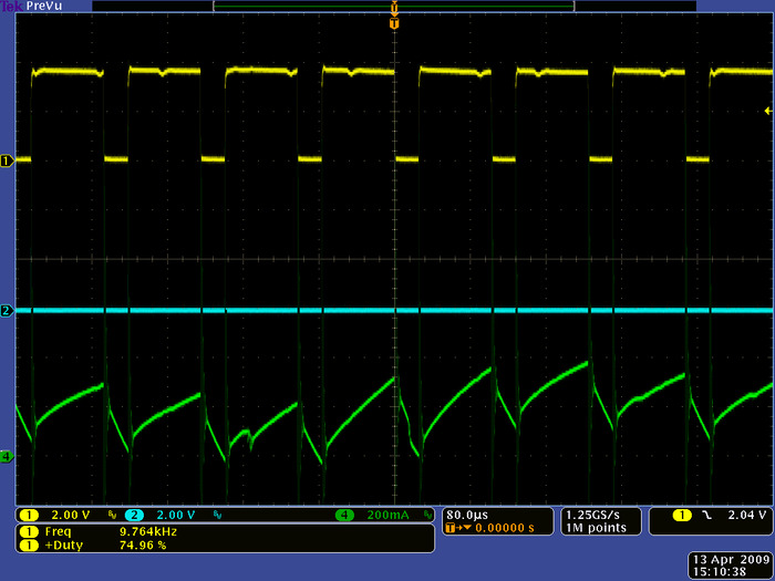 |
Motor outputs M1A (blue) and M1B (yellow) for driving “forward” at 75% duty cycle (OCR0B=191, OCR0A=0). The green channel shows motor current. |
|---|
If you use the Pololu AVR library, the equivalent function call would be set_m1_speed(191) (see the Pololu AVR command reference for more information).
You can see that the M1B output is high 75% of the time and low 25% of the time, and the M1A output is low 100% of the time. While M1B is high, the motor is being driven forward, and while M1B is low, the motor is braking. The net effect is that the motor speed is approximately 75% of its full speed at the supplied motor voltage.
The green line shows the current flowing through the motor. During the high period of M1B’s duty cycle, the current ramps up as the motor draws current from the driver, and during the low period of the duty cycle the current drops as the motor brakes. The motor used for this test is particularly noisy at high speeds (note that the current draw is not always the same from one PWM cycle to the next).
M1_reverse(63);
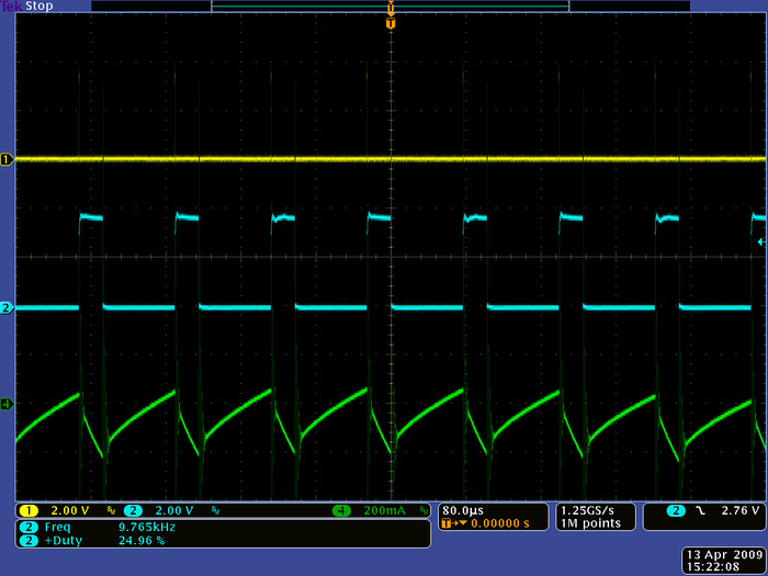 |
Motor outputs M1A (blue) and M1B (yellow) for driving “reverse” at 25% duty cycle (OCR0B=63, OCR0A=0). The green channel shows motor current. |
|---|
If you use the Pololu AVR library, the equivalent function call would be set_m1_speed(-63). (see the Pololu AVR command reference for more information).
Here the M1A output is high for 25% of the time and low for 75% of the time, and the M1B output is low 100% of the time. While M1A is high, the motor is being driven in reverse, and while M1A is low, the motor is braking. The net effect is that the motor speed is approximately 25% of its full speed at the supplied motor voltage.
The green line shows the current flowing through the motor. Note that the zero point of this has been moved up since the current is flowing in the opposite direction when the motor is moving in reverse. At lower speeds, the motor noise decreases and the current draw does not change much from one PWM cycle to the next.
7. Using the Trimmer Pot for Motor Control
The following sample program uses the motor control functions defined in Section 5 to drive the motors in response to the trimmer potentiometer position. Motors 1 and 2 transition linearly from full forward to stationary to full reverse as the potentiometer voltage varies from 0 to 5 V. This program uses the ATmega48/168/328’s analog-to-digital converter to determine the position of the potentiometer.
#include <avr/io.h>

int main()
{
	motors_init();


	// ***** ADC INITIALIZATION *****

	// On the Orangutan and 3pi, the user trimpot can be optionally jumpered
	// to ADC7 using a blue shorting block; the Orangutan and 3pi ship
	// with this shorting block in place (this shorting block is required
	// by this program).  On the Baby Orangutan, the trimpot is permanently
	// connected to ADC7.

	ADCSRA = 0x87;		// bit 7 set: ADC enabled
						// bit 6 clear: don't start conversion
						// bit 5 clear: disable autotrigger
						// bit 4: ADC interrupt flag
						// bit 3 clear: disable ADC interrupt
						// bits 0-2 set: ADC clock prescaler is 128

	ADMUX = 0x07;		// bit 7 and 6 clear: voltage ref is Vref pin
						// bit 5 clear: right-adjust result (10-bit ADC)
						// bit 4 not implemented
						// bits 0-3: ADC channel (channel 7)


	while (1)			// loop forever
	{
		long sum = 0;
		unsigned int avg, i;

		// Here we accumulate 500 conversion results to get an average ADC.
		// According to the ATmegaxx8 datasheet, it takes approximately 13
		// ADC clock cycles to perform a conversion.  We have configured
		// the ADC run at IO clock / 128 = 20 MHz / 128 = 156 kHz, which
		// means it has a conversion rate of around 10 kHz.  As a result,
		// it should take around 50 ms to accumulate 500 ADC samples.
		for (i = 0; i < 500; i++)
		{
			ADCSRA |= ( 1 << ADSC );           // start conversion
			while ( ADCSRA & ( 1 << ADSC ))    // wait while converting
				;
			sum += ADC;     // add in conversion result
		}
		avg = sum / 500;    // compute the average ADC result

		// set motors based on trimpot position (middle value = motor speed 0)
		//  avg is a 10-bit value and hence ranges from 0 to 1023
		if (avg <= 511)
		{
			M1_forward((511 - avg) / 2);
			M2_forward((511 - avg) / 2);
		}
		else
		{
			M1_reverse((avg - 512) / 2);
			M2_reverse((avg - 512) / 2);
		}
	}

	return 0;
}
8. Differences between the Orangutan LV-168 and TB6612FNG-Based Controllers
Everything mentioned so far in this application note applies to both the Orangutan LV-168 and the TB6612FNG-based controllers, but there are some key motor control differences that need to be noted:
| Orangutan LV-168 | Baby Orangutan B, Orangutan SV-xx8, and 3pi robot | |
|---|---|---|
| motor voltage | 2-5 V | 6-13.5 V |
| motor current per channel | 2 A continuous, 5 A peak | 1 A continuous, 3 A peak |
| maximum PWM frequency | 10 kHz | 80 kHz |
The Orangutan LV-168’s performance degrades for PWM frequencies above 10 kHz, which is why the examples in this document use 10 kHz PWMs. However, the TB6612FNG motor driver can handle PWM frequencies as high as 80 kHz. To achieve a PWM frequency of 80 kHz on the ATmega48/168/328P, you need to set:
TCCR0B = TCCR2B = 0x01;
in the motors_init() function (rather than TCCR0B = TCCR2B = 0x02). This clocks the timers off of the 20 MHz system clock directly. Increasing the PWM frequency from 10 kHz to 80 kHz has the benefit of pushing it outside the range of human hearing, thereby eliminating PWM-induced motor whining, but it also increases power losses due to switching, which can cause the motor drivers to heat up faster and potentially trigger thermal shutdown sooner.
Note that you can safely decrease the PWM frequency below 10 kHz on both the Orangutan LV-168 and Baby Orangutan B by using larger timer clock prescalers (e.g. a prescaler of 64 produces a PWM frequency of 1.25 kHz). This decreases switching power losses and can produce a more linear relationship between PWM duty cycle and motor speed, but it could lead to choppier motor motion.
Another difference is the TB6612FNG-based controllers can set the motor driver outputs to a high-impedance state that lets the motor coast instead of brake. The Orangutan LV-168 does not support high-impedance driver outputs.
9. Dealing with Motor Noise
One major drawback to working with motors is the large amounts of electrical noise they produce. This noise can interfere with your sensors and can even impair your microcontroller by causing voltage dips on your regulated power line. Large enough voltage dips can corrupt the data in microcontroller registers or cause the microcontroller to reset.
The main source of motor noise is the commutator brushes, which can bounce as the motor shaft rotates. This bouncing, when coupled with the inductance of the motor coils and motor leads, can lead to a lot of noise on your power line and can even induce noise in nearby lines.
There are several precautions you can take to help reduce the effects of motor noise on your system:
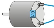 |
1) Solder capacitors across your motor terminals. Capacitors are usually the most effective way to suppress motor noise, and as such we recommend you always solder at least one capacitor across your motor terminals. Typically you will want to use anywhere from one to three 0.1 µF ceramic capacitors, soldered as close to the motor casing as possible. For applications that require bidirectional motor control, it is very important that you do not use polarized capacitors!
If you use one capacitor, solder one lead to each of the motor’s two terminals as shown to the right above.
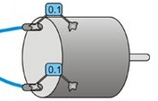 |
For greater noise suppression, you can solder two capacitors to your motor, one from each motor terminal to the motor case as shown in the picture to the right.
For the greatest noise suppression, you can solder in all three capacitors: one across the terminals and one from each terminal to the motor case.
2) Keep your motor and power leads as short as possible. You can decrease noise by twisting the motor leads so they spiral around each other.
3) Route your motor and power wires away from your signal lines. Your motor lines can induce currents in nearby signal lines. We have observed voltage spikes as high as 20 V induced in completely separate circuits near a noisy motor.
4) Place decoupling capacitors (also known as “bypass capacitors”) across power and ground near any electronics that you want to isolate from noise. The closer you can get them to the electronics, the more effective they will be, and generally speaking, the more capacitance you use, the better. We recommend using electrolytic capacitors of at least several hundred µF. Note that electrolytic caps are polarized, so take care to install them with the negative lead connected to ground and the positive lead connected to VIN, and make sure you choose one with a voltage rating high enough to tolerate the noise spikes you are trying to suppress. A good rule of thumb is to select one that is rated for at least twice your input voltage.


Home | Forum | Blog | Support | Ordering Information | Lists | Distributors | BIG Order Form | About | Contact
© 2001–2026 Pololu Corporation
