MMA7260QT 3-Axis Accelerometer ±1.5/2/4/6g

Our popular triple-axis accelerometer is a basic carrier board for the Freescale MMA7260QT XYZ-axis accelerometer, a great low-g sensor with adjustable sensitivity from ±1.5 g to ±6 g. Our breakout board includes a 3.3 V regulator for easy integration into 5 V microcontroller projects, and the unit is smaller than competing products, all at a lower price.
Recommended replacements: MMA7361L 3-Axis Accelerometer ±1.5/6g with Voltage Regulator and MMA7341L 3-Axis Accelerometer ±3/11g with Voltage Regulator.
| Description | Specs (6) | Pictures (4) | Resources (1) | FAQs (1) | On the blog (0) | Distributors (0) |
|---|
Note: The MMA7260QT has been discontinued by Freescale, so this carrier board has been replaced by the MMA7361L 3-Axis Accelerometer ±1.5/6g with Voltage Regulator and MMA7341L 3-Axis Accelerometer ±3/11g with Voltage Regulator.
 |
Overview
This three-axis accelerometer is essentially a carrier board or breakout board for Freescale’s MMA7260QT MEMS (micro-electro-mechanical systems) accelerometer; we therefore recommend careful reading of the MMA7260QT datasheet (199k pdf) before using this product. The MMA7260QT is a great IC, but its small, leadless package makes it difficult for the typical student or hobbyist to use. The device also operates at 2.2 V to 3.6 V, which can make interfacing difficult for microcontrollers operating at 5 V. This carrier board addresses both issues while keeping the overall size as compact as possible.
Using the sensor
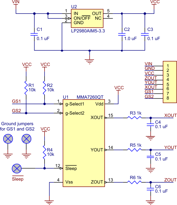
The schematic for the 3-axis accelerometer is shown below. The device can be powered directly through the Vcc/3.3 V pin using a supply that is within the MMA7260QT’s acceptable power supply range of 2.2 V to 3.6 V. Alternatively, the board can be powered by higher voltages, up to 16 V, using the VIN pin, which connects to a low-dropout 3.3 V regulator. In this configuration, the Vcc/3.3 V pin can serve as an output to be used as a reference voltage or power source for other low-power devices (up to around 50 mA, depending on the input voltage).
The sensitivity selection pins GS1 and GS2 are pulled up to the Vcc line, making the default sensitivity 6g; these pins can be pulled low by a microcontroller or through jumpers. For 5 V microcontroller applications, the lines should not be driven high. Instead, the microcontroller I/O pin can emulate an open-drain or open-collector output by alternating between low output and high-impedance (input) states. Put another way, if you are using a 5 V microcontroller, you should make your sensitivity selection I/O lines inputs and rely upon the internal pull-ups on the GS1 and GS2 lines if you want them to be high. It is always safe for you to drive these lines low.
Each of the three outputs is an RC-filtered analog voltage that ranges from 0 to Vcc. For 5 V applications, the outputs will range from 0 to 3.3 V. The 3.3 V output can be used as a reference for analog-to-digital converters to gain full resolution samples. Otherwise, your conversions will be limited to 66% of the full range (e.g. an 8-bit ADC will yield numbers from 0 to 168).
 |
Specifications
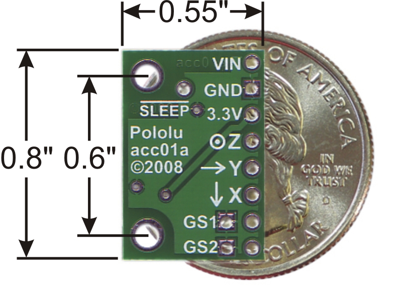
- Dimensions: 0.8" x 0.55" x 0.11" (without header pins)
- Operating voltage: 3.3-16 V
- Supply current: 1.35 mA
- Output format: 3 analog voltages (one signal for each axis)
- Output voltage range: 0-Vcc (0-3.3 V for VIN > 3.3 V)
- Sensitivity range: ±1.5g, 2g, 4g, or 6g (selectable using pins GS1 and GS2; default is ±6g)
- Weight without header pins: 0.030 oz (0.85 g)
Included components
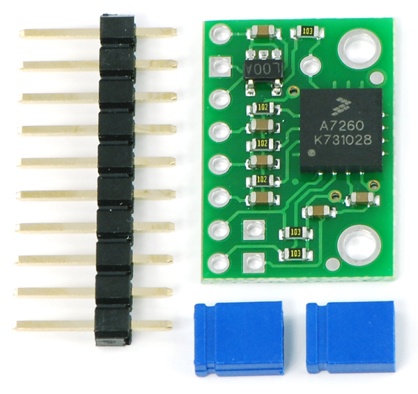
A 10×1 strip of 0.1" header pins and two shorting blocks are included, as shown in the left picture below. These components do not come soldered in. You can break the strip into sub-strips and solder them in as desired, or you can solder wires directly to the board for more compact installations. The shorting blocks can be used as sensitivity range selectors as shown in the right picture below, or you can simply control the sensitivity range by using a microcontroller to drive the appropriate range-selector pins low.
|
|
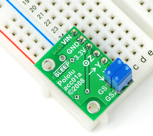
Having both jumpers on selects for a range of ±1.5g; GS2 jumper on and GS1 jumper off selects for ±2g; GS1 jumper on and GS2 jumper off selects for ±4g; both jumpers off selects for a range of ±6g.
| GS1 Jumper | GS2 Jumper | Range |
| ON | ON | ±1.5g |
| off | ON | ±2g |
| ON | off | ±4g |
| off | off | ±6g |
Related products


Home | Forum | Blog | Support | Ordering Information | Lists | Distributors | BIG Order Form | About | Contact
© 2001–2026 Pololu Corporation
