Pololu Blog » User Profile: David »
Posts by David
You are currently viewing a selection of posts from the Pololu Blog. You can also view all the posts.
Popular tags: community projects new products raspberry pi arduino more…
Firmware update for the Micro Maestro to fix position update bug
 |
We have released firmware version 1.04 for the Micro Maestro 6-Channel USB Servo Controller.
This update fixes a bug where receiving any serial command via TTL serial or the Maestro’s USB virtual serial port could potentially interfere with the Maestro’s servo update routine. The servo update routine is responsible for smoothly changing the position of each servo over time while respecting the Maestro’s configurable speed and acceleration limits. Because of the bug, receiving a serial command could cause position updates for some servos to happen too soon or to be skipped entirely. Repeated serial commands at high baud rates could also trap the Maestro in the servo update routine, causing it to become unresponsive.
This bug has been present since we first released the Micro Maestro almost 10 years ago in November of 2009, but its effects tend to be subtle, and we only learned about it a few weeks ago when a customer brought it to our attention.
This bug does not affect the 12-channel, 18-channel, and 24-channel Mini Maestros, so there is no corresponding update for them. The latest Mini Maestro firmware version is still 1.03.
For information about how to upgrade your 6-channel Micro Maestro, see the “Upgrading Firmware” section of the Maestro user’s guide.
Firmware update for Tic Stepper Motor Controllers, with new features including limit switches and homing
 |
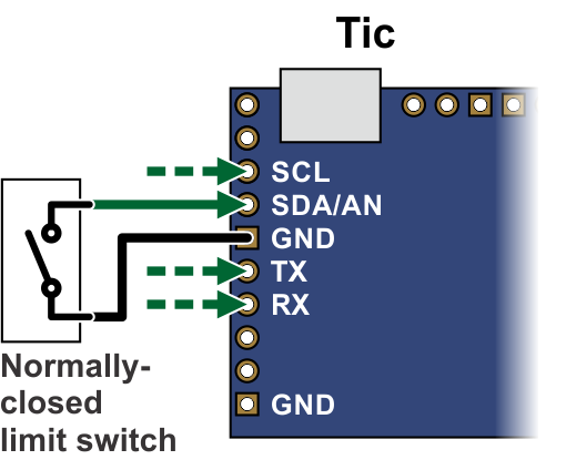 |
Connecting a limit switch to the Tic (SCL, SDA, TX, and RX pins). |
|---|
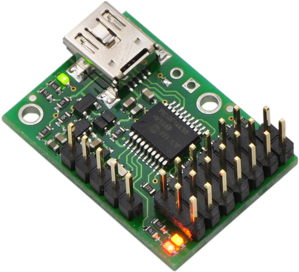
To go along with last week’s release of the Tic T249, we have also released a new version of the Tic firmware (version 1.06) for all Tic stepper motor controllers that adds several new features.
By popular demand, this new firmware version adds support for limit switches: any of the Tic control pins (SCL, SDA, TX, RX, or RC) can be configured as a digital input for a forward or reverse limit switch. When the limit switch is active, the Tic abruptly shuts down any movement in the specified direction, but allows the stepper motor to move in the other direction. You can use limit switches to help prevent your system from leaving its desired range of motion.
If you configure a limit switch, you can use the Tic’s new homing procedure. The new “Go home” command, which is available over serial, I²C, and USB, starts the homing procedure. The Tic will move in the direction specified by the command until it hits a limit switch for that direction. Then it will change directions, move until the limit switch deactivates, and set its current position to 0. The stepping speeds used by the Tic during the homing procedure are configurable.
You can also use the homing feature automatically, without sending a command. If automatic homing is enabled, the Tic performs the homing procedure whenever it is being commanded to go to a specific position but it is uncertain of its current position (e.g. immediately after motor power is applied). This feature can be handy if you are controlling the position of your stepper motor using an RC, analog, or quadrature encoder signal.
We have added a new section to the Tic user’s guide with detailed instructions for setting up limit switches and homing.
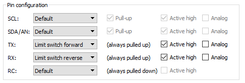 |
Example pin configuration for a Tic with limit switches. |
|---|
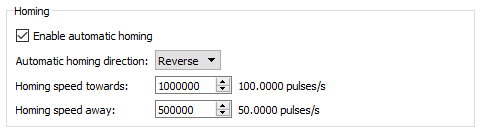 |
New homing settings added in Tic firmware version 1.06. |
|---|
The new firmware version also adds several features to the Tic’s TTL serial interface that make it more usable in systems with large numbers of Tics and in half-duplex serial busses. Specifically, it adds support for an alternative device number so any Tic can optionally be addressed by two different device numbers, and it adds an option to enable 14-bit device numbers so you can have more than 128 devices on a serial bus. The new firmware version also has an option to encode its serial responses using only bytes between 0 and 127, which can be useful in setups where the serial response from one Tic will be seen by other Tic devices, and you don’t want it to be misinterpreted as a command. We also implemented several changes to make the Tic less susceptible to noise on the serial lines, and you can now enable CRC bytes for serial responses sent by the Tic so that you can confirm the data you received matches what the Tic sent.
The Tic T249 was released with the latest firmware, so it has all of these new features, and we will be upgrading our existing Tics to this firmware version as we manufacture more. To gain access to these new features on your existing Tic controllers, you can download the latest configuration software and upgrade your device’s firmware to version 1.06. For more information, see the firmware upgrade instructions in the Tic user’s guide.
Related products


New product: Tic T249 USB Multi-Interface Stepper Motor Controller

I am excited to announce the release of the Tic T249 USB Multi-Interface Stepper Motor Controller, the fourth model in our line of Tic Stepper Motor Controllers. The Tic T249, which is based on the TB67S249FTG IC from Toshiba, features a broad 10 V to 47 V operating range and can deliver up to approximately 1.8 A per phase without a heat sink or forced air flow, making it our highest-power Tic yet. In addition to the array of high-level features offered by the other members of our Tic family, the Tic T249 offers access to several innovative features of the TB67S249FTG driver. Continued…
Shiny new software for the Jrk G2 USB Motor Controllers with Feedback
 |
I am happy to announce that we have released version 1.2.0 of the configuration software for the Jrk G2 USB Motor Controllers with Feedback.
This release contains a large number of new features for our graphical user interface (GUI) software that let you have more information and control while you are setting up a feedback system with the Jrk.
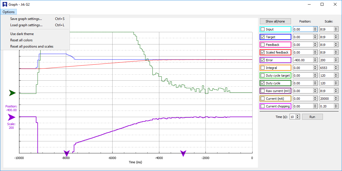
The graph window received the most striking update: you can now use the mouse to vertically move and zoom the different plots independently of each other. You can change the colors of the plots and save your settings to a file so you don’t have to redo them the next time you start the utility. Colored indicator arrows appear at the top and/or bottom of the graph if one of the values you are plotting is too high or low to be plotted.
The variables shown in the status tab can now be moved into their own, separate window, so you can see them at all times without having to switch back to the status tab. Similarly, the “Manually set target” interface is now visible from every tab, so you can quickly test your feedback system after changing any setting. We added a “Center” button that sets the Jrk’s target to 2048, and we added a moving red dot to the target slider that shows the scaled feedback if feedback is enabled. If feedback is not enabled, the dot is green and shows the duty cycle instead.
The “Apply settings” button now has a blue background and a label to its left when it is enabled, to make it more obvious that you should apply your settings.
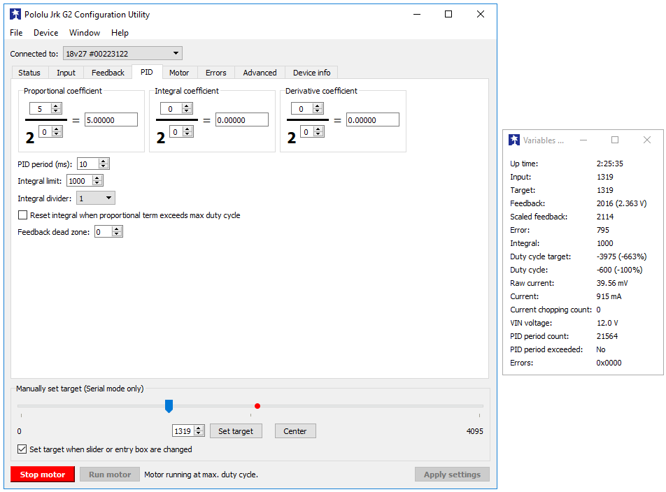 |
The main window and the variables window in the Jrk G2 Configuration Utility (version 1.2.0). |
|---|
A brief history of Jrk software development
We developed the software for our original Jrk 21v3 and Jrk 12v12 controllers back in 2009. We used the C# language and the WinForms GUI API from Microsoft since that is what we were familiar with, but unfortunately those choices basically locked us into only having the software work on Windows. While you can compile and run C# code on Linux and macOS using Mono, and Mono does have an implementation of the WinForms API, that WinForms implementation was far from adequate. It worked on x86 Linux machines, crashed immediately on ARM Linux machines, and kind of ran but was totally unusable on macOS machines. I reported a few bugs to the Mono project, and the only response I got was that WinForms is no longer being developed actively. We never released Jrk software for Linux, though we did release Maestro and Simple Motor Controller software for x86 Linux using Mono. People have asked us many times over the years about running our software on a Raspberry Pi, and for our C#/WinForms GUI software we always had to tell them that it was not possible because there was no good implementation of the WinForms API for that platform.
Starting with the Wixel in 2011, we switched to using C, C++, and Qt for our configuration software. Qt is a giant cross-platform C++ library with many components. For us, the most important component is Qt Widgets, which makes it easy to develop a cross-platform GUI with the standard elements that people expect, like windows, menus, buttons, checkboxes, and text fields. There are wrappers for accessing Qt in different languages, but we chose to write our GUI software in C++ so that it can directly access Qt, and because C++ code is easier to deploy than a lot of other languages that might require a virtual machine or interpreter. Qt works well on Windows, macOS, and Linux – including on the Raspberry Pi. While we sometimes encounter bugs in Qt or overly-rigid APIs that lack important features, we are usually able to work around those issues and get a good result.
Along with C++ and Qt, we use the C language to write low-level libraries for actually talking to the USB devices. The upper layer of these libraries takes device-specific commands like “set target to 2800” and translates them into USB commands. The lower layer takes the USB commands and passes them to an appropriate USB API provided by the operating system. This is a nice way to split up the software: the device layer knows about the device but doesn’t know about the operating system, and the USB abstraction layer knows about the operating system but doesn’t know about the device.
The Wixel software developed in 2011 used its own minimal USB abstraction layer written in C. The first versions of p-load, developed in 2014 for our P-Star 25K50 Micro, did something similar. In 2015, I built on the lessons learned from these earlier projects to develop a much better USB abstraction library called libusbp. This new library has been working great for us since then, and powers all of the USB communication in the latest versions of p-load, the Pololu USB AVR Programmer v2 software, the Tic software, and the Pololu Jrk G2 software.
In 2017, I developed another piece of the stack: nixcrpkgs. The nixcrpkgs project solves the problem of reliably compiling our portable C/C++ source code into actual executables and installers that work on a variety of different systems. With nixcrpkgs, I can compile our software for Windows, macOS, and Linux (32-bit, 64-bit, and ARM) by just running a single command on one computer. It allows me to control the exact versions of all the dependencies that go into the software. I no longer have to worry about the versions of tools and libraries installed on my development machines. I also do not have to worry about the software installed on the end user’s machine: software compiled with nixcrpkgs uses static linking so all of its dependencies (except for certain things provided by the operating system) are linked directly into the executable. The download for the Jrk G2 software for the Raspberry Pi generated by nixcrpkgs is only 6 MB (compressed), and it installs just 4 files.
Prior to nixcrpkgs, we only provided binary downloads for Windows and macOS. It was difficult to produce these downloads because we relied on third-party software distribution systems like MSYS2 and Homebrew to provide binary versions of the libraries we depended on, and we didn’t have much control over those systems. We required Linux users to compile the software and its dependencies (like libusbp) themselves. Compiling software from source can be a pretty error-prone process: we strive to make our software portable, but it’s hard to test enough combinations of compiler and library versions to avoid all the issues that might come up.
The Jrk G2 software is open source and comes with build instructions for many platforms. I am hoping that this will allow people to do cool things in the future, such as translating the GUI text into their native language, adding buttons to perform custom commands, or using the code in their own software to control the Jrk. It should also provide some confidence that you will be able to use the Jrk in long-term applications and recompile the software for future operating systems.
You can download the new software from the Jrk G2 Motor Controller User’s Guide or the “Resources” tab on a Jrk G2 product page. If you need help using the software or troubleshooting your system, please post on our forum. If you have feedback or additional feature requests for the software, let us know in the comments.
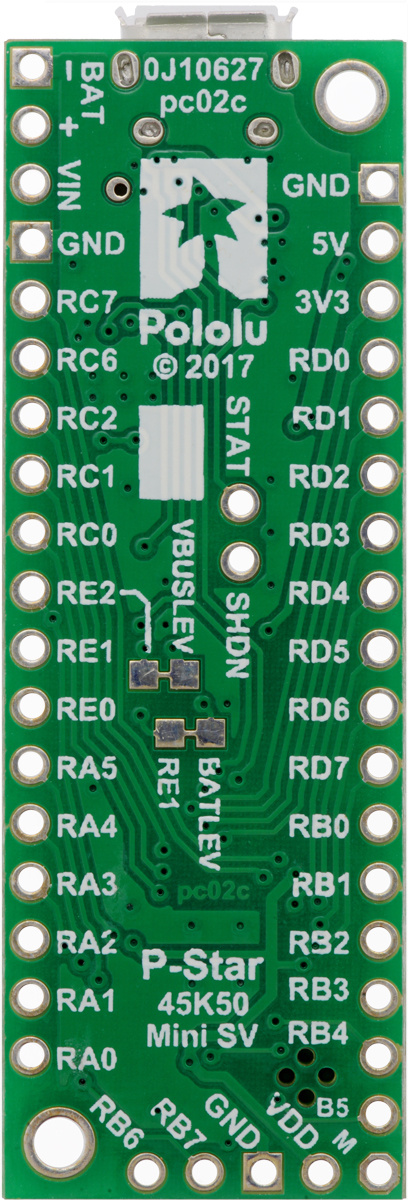
New product: P-Star 45K50 Mini SV
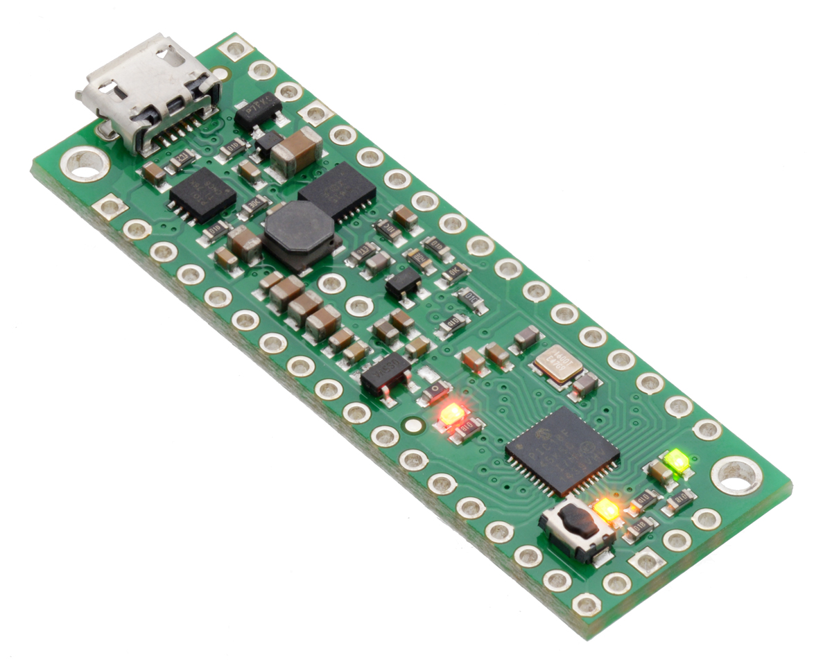 |
I am excited to announce our new product, the Pololu P-Star 45K50 Mini SV, which is the second member of our P-Star family of programmable controllers based on the PIC18 microcontrollers from Microchip. The P-Star 45K50 Mini SV features a user-programmable PIC18F45K50 microcontroller (32 KB of flash, 2 KB of RAM, full-speed USB), a USB bootloader, and a switching step-down regulator that allows it to be powered from 5 V to 36 V.
The P-Star 45K50 Mini SV is very similar to the smaller P-Star 25K50 Micro, but is bigger and better, with 11 more I/O pins (for a total of 30), a more capable 5 V regulator, and several other additional features. The table below lists the main differences between the two P-Stars:
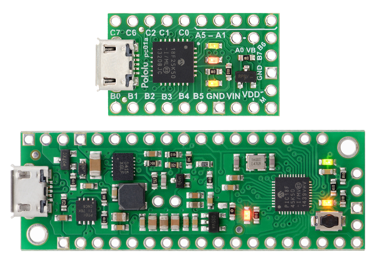 |
P-Star 25K50 Micro (top) and P-Star 45K50 Mini SV (bottom). |
|---|
 |
 | |
| P-Star 25K50 Micro | P-Star 45K50 Mini SV | |
|---|---|---|
| Microcontroller: | PIC18F25K50 | PIC18F45K50 |
| User I/O lines: | 19 | 30 |
| Analog inputs: | 14 | 25 |
| Reset button: |  |
|
| Operating voltage: | 5.5 V to 15 V | 5 V to 36 V |
| Regulator type: | linear | switching step-down |
| Regulated current:(1) | 100 mA | 500 mA |
| Auxiliary 3.3 V regulator: | |
|
| Dimensions: | 1″ × 0.6″ | 2.0″ × 0.7″ |
1 These values are rough approximations for comparison purposes. Available current depends on input voltage, current consumed by the board, ambient conditions, and regulator topology.
Although we have been using PIC microcontrollers since our very first product, these two P-Stars are our first products where the PIC microcontroller can be programmed by the user. You can program the P-Star in C or assembly with the MPLAB X IDE, or you can use Microchip’s new online IDE, MPLAB Xpress. The P-Star User’s Guide has instructions for getting started with those environments.
You can load programs onto the P-Star via its proprietary USB bootloader using our open source software that is available for Windows, Linux, and Mac. The bootloader uses 8 KB of flash memory, leaving 24 KB for the user. Alternatively, an ICSP programmer can erase the bootloader and access the full 32 KB of program memory. (Since the bootloader is not recoverable, we recommend this option only for those who are comfortable programming exclusively with an external programmer.)
Both P-Star boards feature a precision 16 MHz crystal, a USB Micro-B connector, and three user-controllable LEDs. A voltage regulator and power selection circuit allow the board to be powered from either USB or an external voltage source.
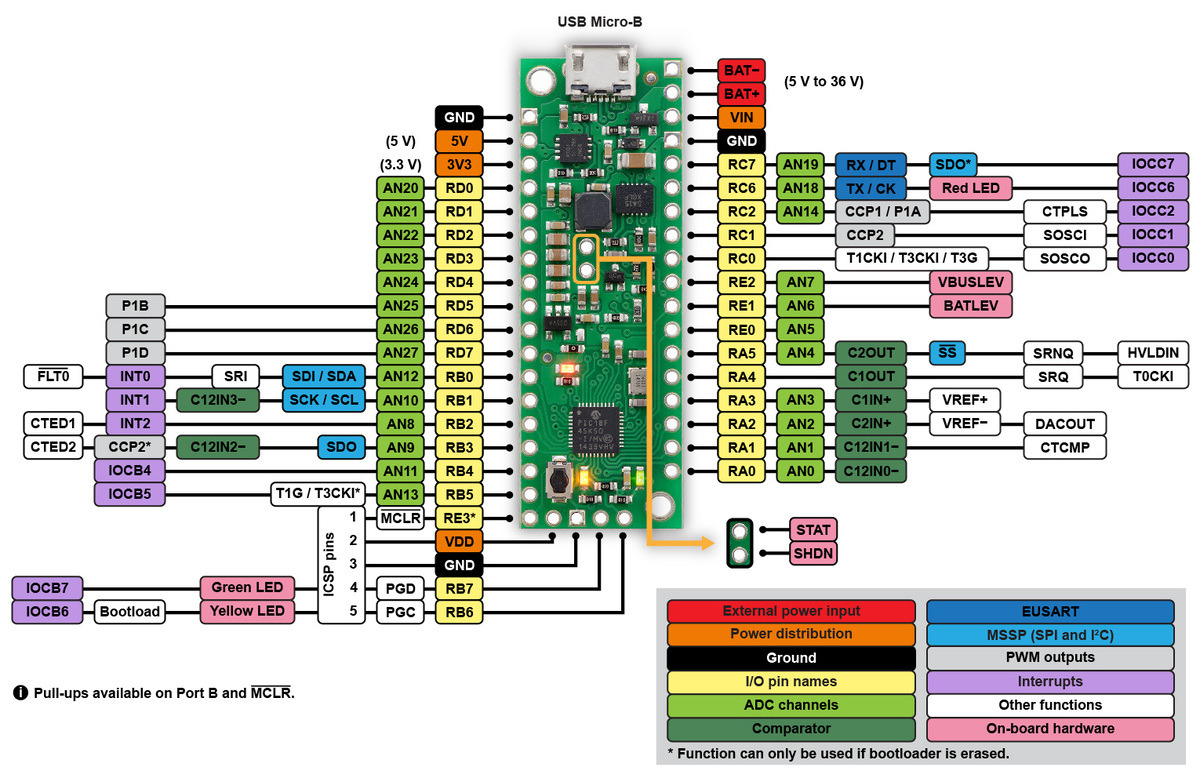 |
P-Star 45K50 Mini SV pinout diagram. |
|---|
Compared to the popular ATmega32U4 microcontroller, the PIC18F25K50 and PIC18F45K50 have nearly the same performance and memory capacity, but these PICs also have some compelling features that are missing on the AVR. For example, they use the PIC18 architecture, which has two interrupt priority levels: interrupts can be assigned to either level, and a high-priority interrupt routine can run during a low-priority one. This powerful feature is what enables our Maestro servo controllers to generate precise servo signals while still using low-priority interrupts to assist with serial communication and other tasks. Unlike the ATmega32U4, these PICs can operate at full speed down to 2.7 V (though the brown-out reset on the P-Star is activated at 2.85 V by default).
|
|
The PIC18F25K50 and PIC18F45K50 also feature a 5-bit digital-to-analog converter (DAC), which is a handy feature not available on many 8-bit microcontrollers. We use that DAC to set the stepper motor current limit on our Tic stepper controllers, where the PIC18F25K50 serves as the main processor.
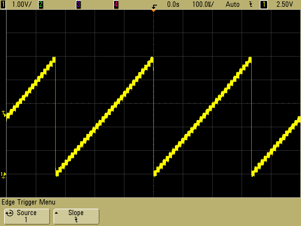 |
A 3 kHz triangle wave generated by the 5-bit digital-to-analog converter (DAC) on the P-Star 25K50 Micro. |
|---|
For more information, check out the P-Star 45K50 Mini SV page.
Related products


New product: Tic T834 USB Multi-Interface Stepper Motor Controller
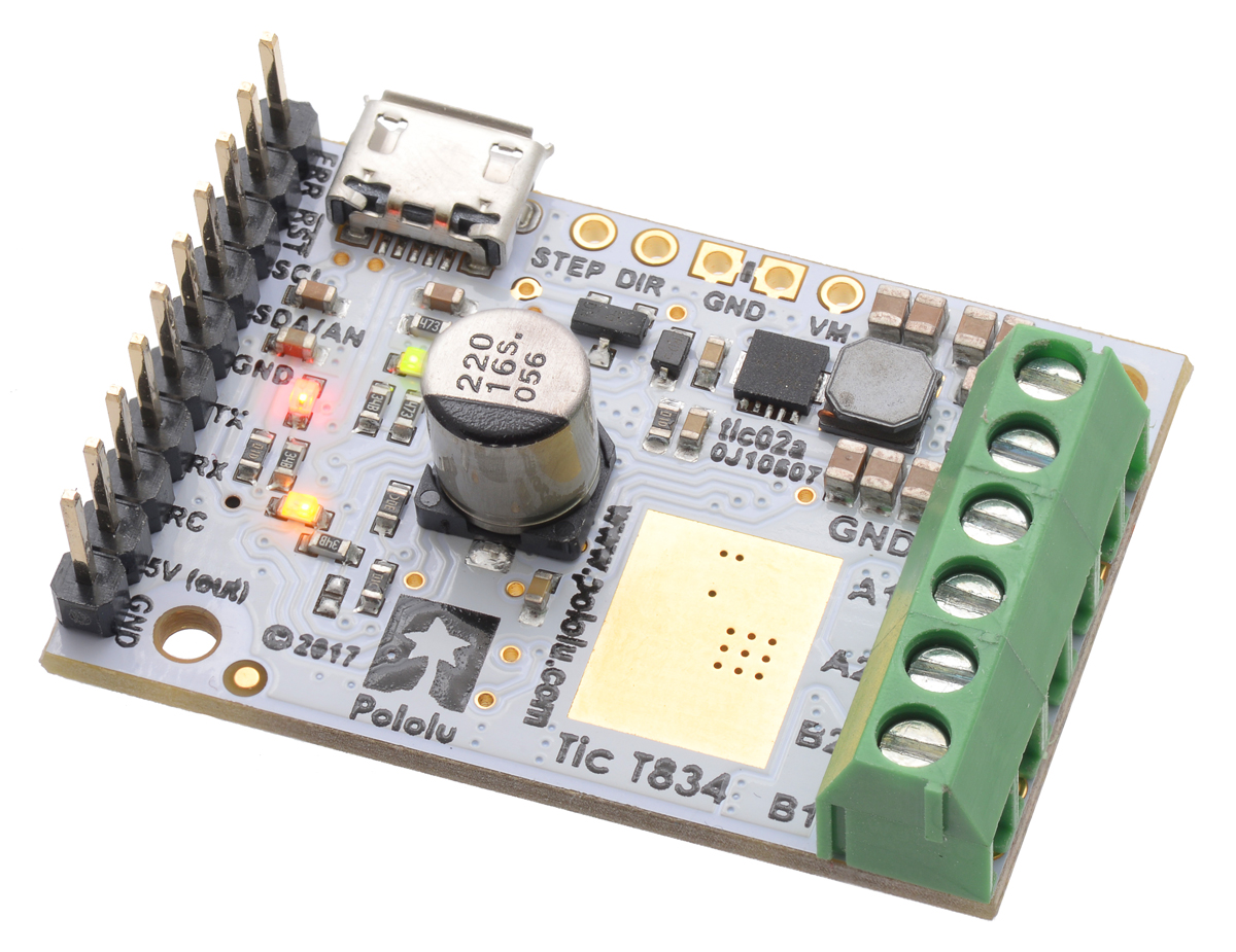 |
I am excited to announce our new product, the Tic T834 USB Multi-Interface Stepper Motor Controller. The Tic T834 is the second member of the Tic family of USB stepper motor controllers. It incorporates a TI DRV8834 driver, can operate from 2.5 V to 10.8 V, and can deliver up to approximately 1.5 A per phase without a heat sink or forced air flow.
Like the Tic T825, the Tic T834 makes basic speed or position control of a stepper motor easy, with support for six high-level control interfaces:
- USB for direct connection to a computer
- TTL serial operating at 5 V for use with a microcontroller
- I²C for use with a microcontroller
- RC hobby servo pulses for use in an RC system
- Analog voltage for use with a potentiometer or analog joystick
- Quadrature encoder input for use with a rotary encoder dial, allowing full rotation without limits (not for position feedback)
 |
Tic T825 and T834 USB Multi-Interface Stepper Motor Controllers. |
|---|
The Tic T834 is available with connectors soldered in or without connectors soldered in.
Related products
Introducing the Tic T825 USB Multi-Interface Stepper Motor Controller
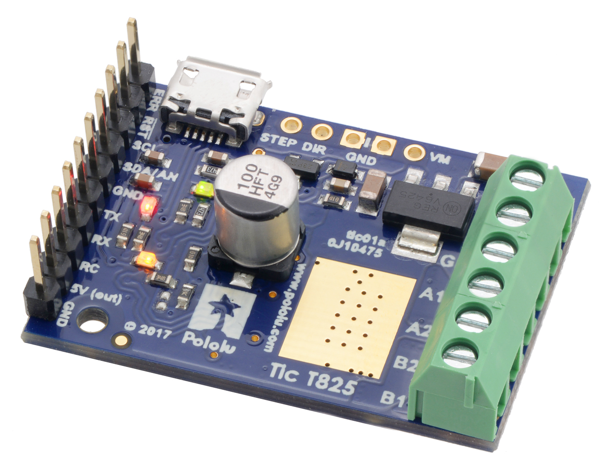 |
I am excited to announce our new product, the Tic T825 USB Multi-Interface Stepper Motor Controller. The Tic makes basic speed or position control of a stepper motor easy, with support for six high-level control interfaces:
- USB for direct connection to a computer
- TTL serial operating at 5 V for use with a microcontroller
- I²C for use with a microcontroller
- RC hobby servo pulses for use in an RC system
- Analog voltage for use with a potentiometer or analog joystick
- Quadrature encoder input for use with a rotary encoder dial, allowing full rotation without limits (not for position feedback)
You can select which of these interfaces you want to use and configure the other settings of the Tic over USB using our free software.
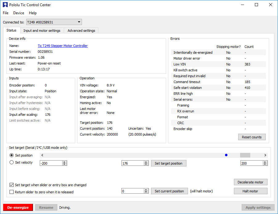 |
The Status tab of the Pololu Tic Control Center. |
|---|
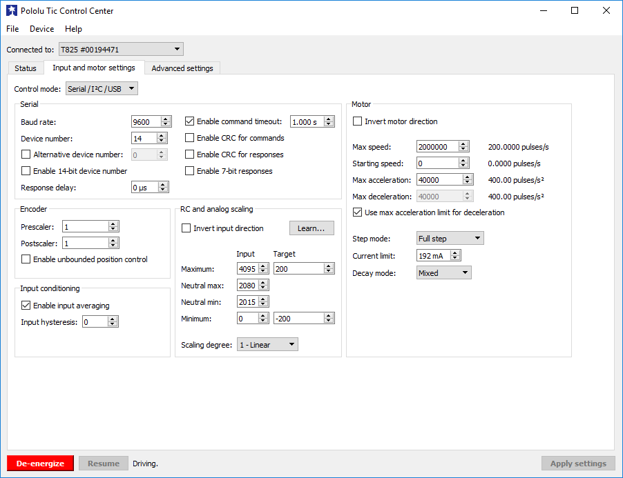 |
The Input and Motor Settings tab of the Pololu Tic Control Center. |
|---|
The Tic T825 can operate from 8.5 V to 45 V and deliver up to approximately 1.5 A per phase continuously without a heat sink or forced air flow. With a digitally adjustable current limit that can be set over USB, serial, or I²C, you can save power while holding position or increase the motor’s torque while it is moving. The Tic offers six different step resolutions, from full step through 1/32-step (32 microsteps per full step). We designed the Tic’s firmware to be capable of taking up to 50,000 microsteps per second, which lets you use those finer microstepping modes while still keeping a high motor speed. The Tic also supports acceleration and deceleration limiting for smooth movements, and very slow speeds down to 1 step every 200 seconds (or 1 step every 1428 seconds with reduced resolution). The Tic T825 is based on the DRV8825 stepper motor driver IC from Texas Instruments (for which we also have a basic carrier board), and we plan to make other versions of the Tic that are based on different drivers with different performance characteristics.
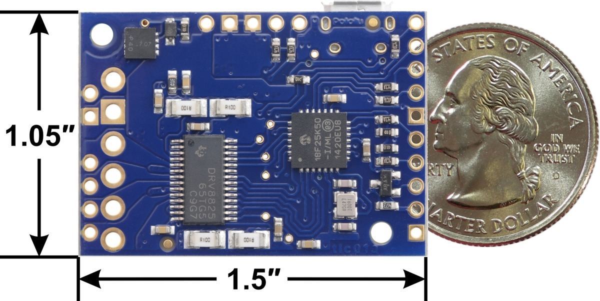 |
Tic T825 USB Multi-Interface Stepper Motor Controller, bottom view with dimensions. |
|---|
The Tic T825 is available with connectors soldered in or without connectors soldered in.
For RC/hobby servos, we have a similar family of products called the Maestro servo controllers. For brushed DC motors, we offer the Simple Motor Controllers and the Jrk Motor Controllers.
Related products

New SK9822 LED strips and panels
 |
We’re excited to offer a series of addressable LED strips and addressable LED panels based on the new SK9822 integrated circuit. Like the APA102C, the SK9822 combines an RGB LED and driver into a single 5050-size package, allowing each pixel to be individually controlled using a simple two-wire SPI protocol.
The SK9822 is almost (see the notes below) a drop-in replacement for the APA102C and is better than it in a few ways, most importantly its built-in constant current control. If you’ve ever tried to power a long chain of LED strips and only connected power at one end, you might have noticed that the far end of the LED strip has a lower voltage across its power rails because of resistance in the long power connections. For LED strips based on the APA102C and WS2812B, the lower voltage makes the light dimmer and redder. With the SK9822, voltage drops like that are less likely to have a visible effect as long as the voltage stays above 3.5 V.
The SK9822’s protocol is very similar to that of the APA102C, but it updates the color that is being shown at a different time. If you replace APA102C LEDs with SK9822 LEDs in a low frame-rate application, you might have to update the code you are using to control the LEDs. The latest version of our APA102 Arduino library works with the SK9822 so you can either use it directly or use it as a reference when writing your own code. The colors generated by the SK9822 look different from the colors generated by the APA102C, so we would not recommend mixing the APA102C and the SK9822 in a single project.
We offer six different kinds of SK9822 LED strip with different LED densities and lengths:
- 1 meter, 30 LEDs (30 LEDs/m)
- 2 meters, 60 LEDs (30 LEDs/m)
- 5 meters, 150 LEDs (30 LEDs/m)
- 1 meter, 60 LEDs (60 LEDs/m)
- 2 meters, 120 LEDs (60 LEDs/m)
- 0.5 meters, 72 LEDs (144 LEDs/m)
We offer SK9822 LED panels in three different sizes:
These new SK9822-based products will replace our older APA102C-based products.
We continue to offer SK6812-based LED strips which also have constant current control but are controlled with a one-wire protocol.
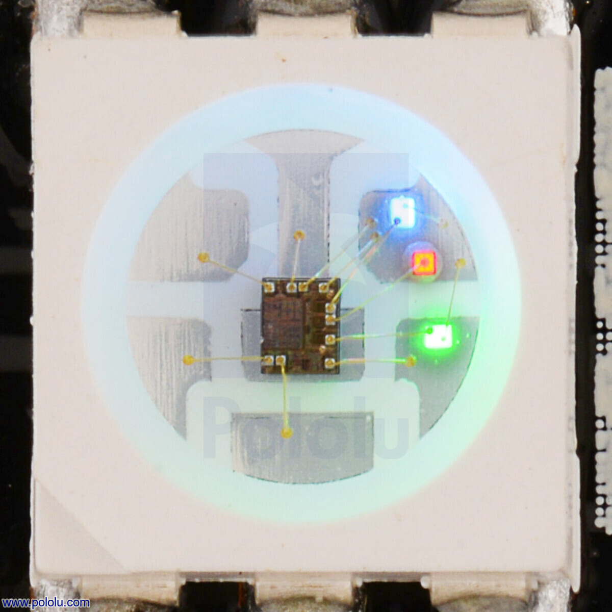 |
Close up of an SK9822, with the red, green, and blue LEDs on at a low brightness. |
|---|
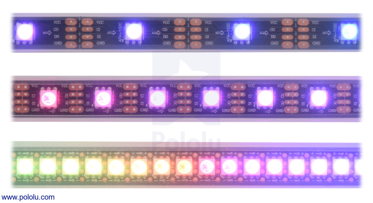
 |
An addressable RGB LED strip (APA102C or SK9822) displaying a rainbow animation. |
|---|
Related products


Ten-Tec 1254 Receiver Display Upgrade Kit
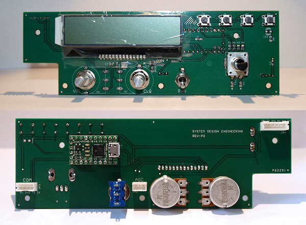 |
Edward Cholakian (call sign KB1OIE) makes and sells a Ten-Tec 1254 Receiver Display Upgrade Kit that is designed to upgrade a Ten-Tec 1254 shortwave radio receiver.
One of the main features of the kit is that it provides a backlit 2×20 character LCD to replace the receiver’s original 5-digit 7-segment display, allowing much more information to be shown. The kit includes a clear plastic window to replace the receiver’s original smoked dark plastic window, and a black plastic display mask. Edward gets both of these pieces made using our custom laser-cutting service.
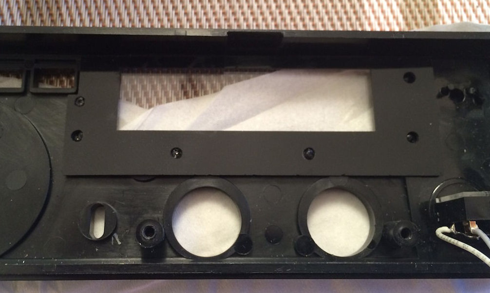 |
Two laser-cut pieces, a clear window and black display mask, shown on top of the Ten-Tec 1254 receiver’s original face plate. |
|---|
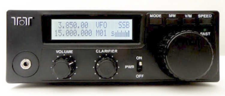 |
Ten-Tec 1254 receiver with Edward Cholakian’s display upgrade kit installed. |
|---|
The display/control board in the kit uses the P-Star 25K50 Micro as its processor. Edward, a consulting engineer who designs embedded hardware and firmware, told us that he chose the P-Star because he was already using a Microchip processor similar to the P-Star’s PIC18F25K50 in one of his previous designs, and it was more economical to buy the P-Star than to hand-assemble his own board. He said the P-Star’s cross-platform USB firmware upgrade software was also a plus since his own bootloading software does not support Linux and macOS.
The kit comes with software for Windows that can control the receiver over USB. The software provides a graphical user interface and uses WinUSB to talk to the P-Star’s native USB interface.
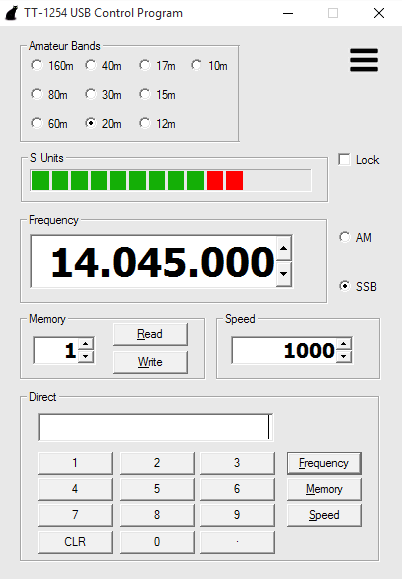 |
USB control program for the Ten-Tec 1254 Receiver Display Upgrade Kit |
|---|
For more information, see the Ten-Tec 1254 Receiver Display Upgrade Kit page.
Related products

New products: Addressable RGB LED strips based on the SK6812
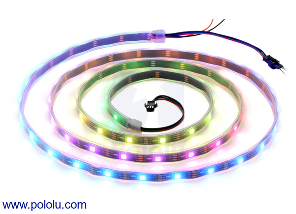 |
We are now selling new addressable RGB LED strips based on the SK6812. These LED strips replace our older WS2812B LED strips. Like the WS2812B, the SK6812 is an RGB LED with an integrated driver that allows independent control over a chain of LEDs using just one I/O line. The main difference between the two drivers is that the SK6812 has constant current control capabilities that let it have a voltage-independent color and brightness over a wide range of voltages, so any voltage drop due to long power lines is less of a concern.
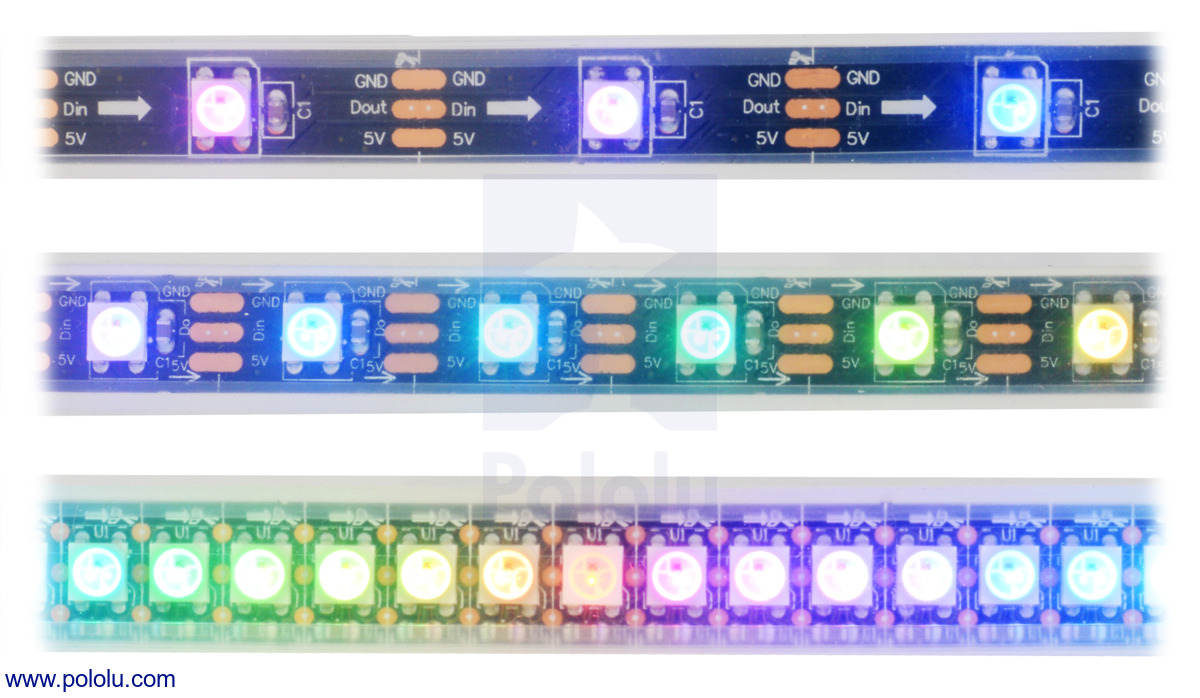 |
LED side of the SK6812-based addressable LED strips, showing 30 LEDs/m (top), 60 LEDs/m (middle), and 144 LEDs/m (bottom). |
|---|
We offer six different kinds of SK6812 LED strip with different LED densities and lengths. Our strips with 30 LEDs per meter are available in three lengths:
We also offer denser SK6812 LED strips that have 60 LEDs per meter:
Our highest density strip has 144 LEDs per meter:
We provide LED strip example code for the Arduino, AVR, and mbed microcontroller platforms. More information about the LED strips and how to use them can be found on the LED strip product page.
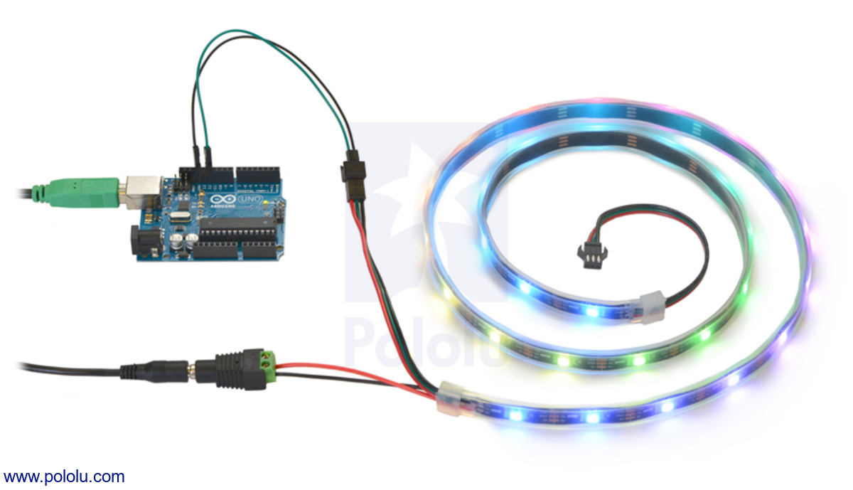 |
Controlling an addressable RGB LED strip with an Arduino and powering it from a 5V wall power adapter. |
|---|
Related products


Home | Forum | Blog | Support | Ordering Information | Lists | Distributors | BIG Order Form | About | Contact
© 2001–2026 Pololu Corporation


