Pololu Blog » Posts tagged “new products” »
Posts tagged “new products” (Page 3)
You are currently viewing a selection of posts from the Pololu Blog. You can also view all the posts.
Popular tags: community projects new products raspberry pi arduino more…
New products: 1.4-7V fine-adjust D30V3xMALx step-down voltage regulators
|
|


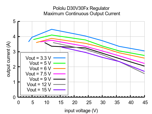
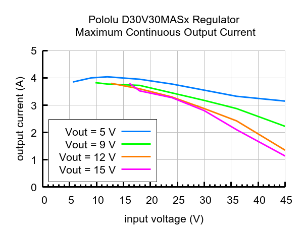
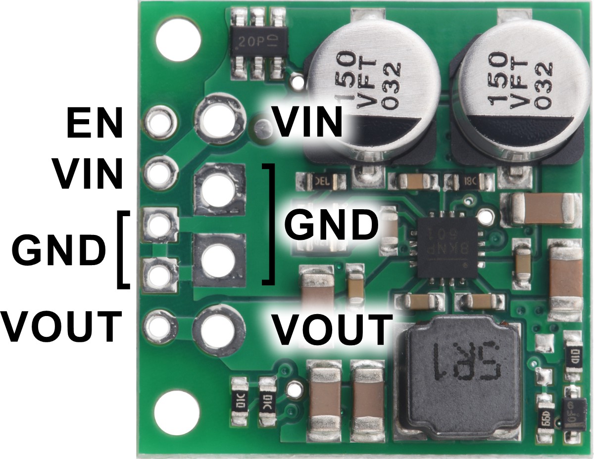
We are now offering lower-voltage versions of our D30V3x step-down voltage regulators with a precision-adjustable 1.4 V to 7 V output. As with the rest of the D30V3x line, these new regulators work with input voltages between 3.3 V and 45 V and can deliver between 1 A and 4.5 A of output current, depending on the input and output voltages. They have very low dropout voltages and feature a power-good output for identifying when the output voltage is not being maintained. They also feature an enable pin with a precise threshold for turning off the regulator, and some of the versions have additional circuitry to offer a precision-adjustable low-voltage cutoff.
 |
 |
Four versions are available with this new 1.4 V to 7 V output range:
- D30V30MAL – compact (0.6″ × 1.0″), double-sided assembly with precision-adjustable output and no low-voltage cutoff.
- D30V30MALCMA – compact (0.6″ × 1.0″), double-sided assembly precision-adjustable output and precision-adjustable low-voltage cutoff.
- D30V33MAL – larger (0.9″ × 1.2″), single-sided assembly with precision-adjustable output and no low-voltage cutoff. The increased heat dissipation from the larger boards let this version deliver slightly more current than the D30V30MAL.
- D30V33MALCMA – larger (0.9″ × 1.2″), single-sided assembly with precision-adjustable output and precision-adjustable low-voltage cutoff. The increased heat dissipation from the larger boards let this version deliver slightly more current than the D30V30MALCMA.
 |
 |
The following table shows all of the members of the D30V3x family:
| Regulator | Output voltage | Typical max output current1 |
Input voltage2 | Adjustable low-voltage cutoff |
Size | Price |
|---|---|---|---|---|---|---|
| #4891: D30V30F3 | 3.3 V | 3.7 A | 3.3 V – 45 V | – | 0.7″ × 0.8″ | $19.95 |
| #4892: D30V30F5 | 5 V | 3.4 A | 5 V – 45 V | $19.95 | ||
| #4893: D30V30F6 | 6 V | 3.3 A | 6 V – 45 V | $20.95 | ||
| #4894: D30V30F7 | 7.5 V | 3 A | 7.5 V – 45 V | $20.95 | ||
| #4895: D30V30F9 | 9 V | 2.9 A | 9 V – 45 V | $20.95 | ||
| #4896: D30V30F12 | 12 V | 2.8 A | 12 V – 45 V | $20.95 | ||
| #4897: D30V30F15 | 15 V | 2.7 A | 15 V – 45 V | $20.95 | ||
| #4873: D30V30MAL | 1.4 V – 7 V | 3.4 A | 3.3 V – 45 V | – | 0.6″ × 1.0″ | $25.95 |
| #4872: D30V30MALCMA | $29.95 | |||||
| #4875: D30V30MAS | 4.2 V – 15 V | 3 A | 4.2 V – 45 V | – | $25.95 | |
| #4874: D30V30MASCMA | $29.95 | |||||
| #4853: D30V33MAL | 1.4 V – 7 V | 3.8 A | 3.3 V – 45 V | – | 0.9″ × 1.2″ | $25.95 |
| #4852: D30V33MALCMA | $29.95 | |||||
| #4855: D30V33MAS | 4.2 V – 15 V | 3.3 A | 4.2 V – 45 V | – | $25.95 | |
| #4854: D30V33MASCMA | $29.95 | |||||
| 1At 30 V in. Actual achievable continuous output current is a function of input and output voltages and is limited by thermal dissipation. | ||||||
| 2Operating voltage must be higher than the set output voltage and is subject to dropout voltage considerations. | ||||||
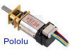
New products: Micro Metal Gearmotors with integrated encoders
|
|
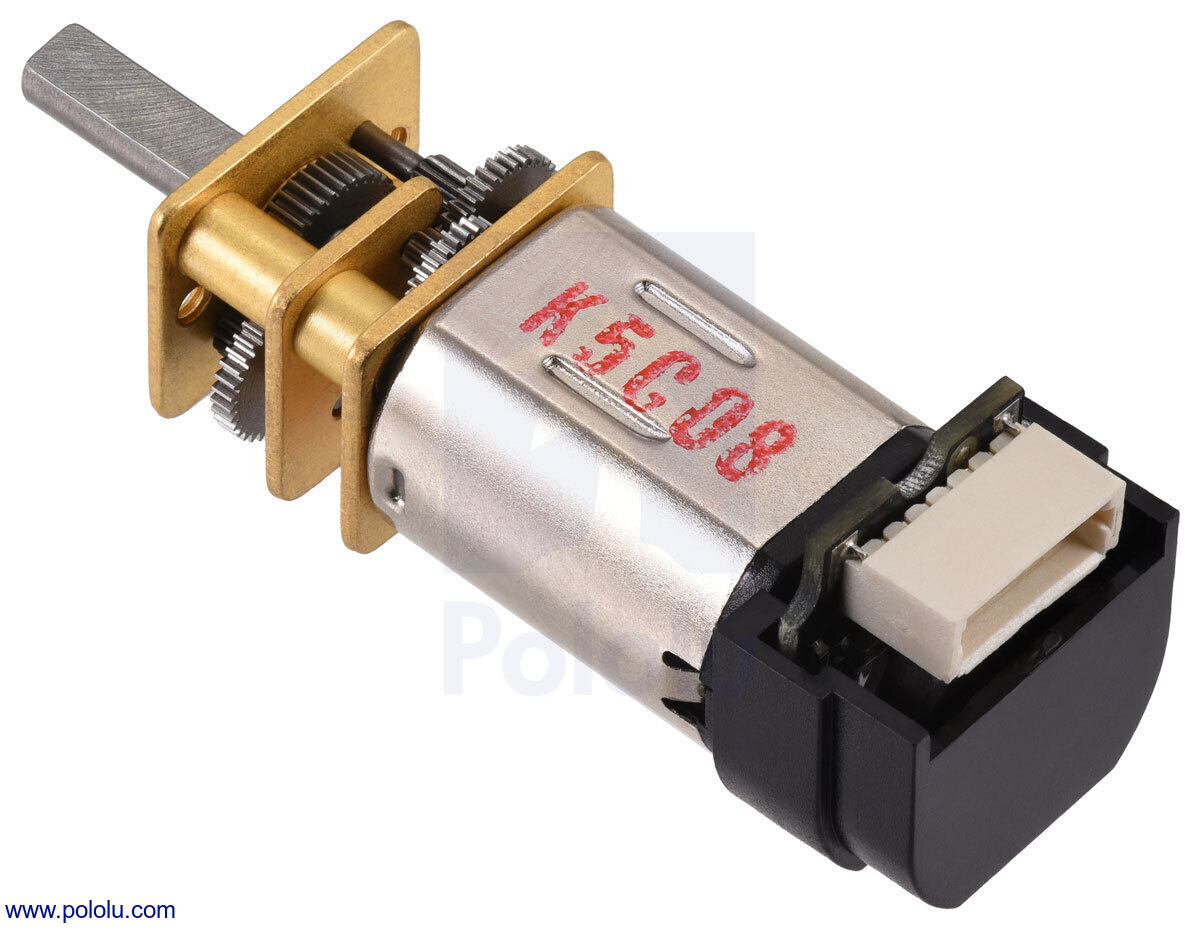
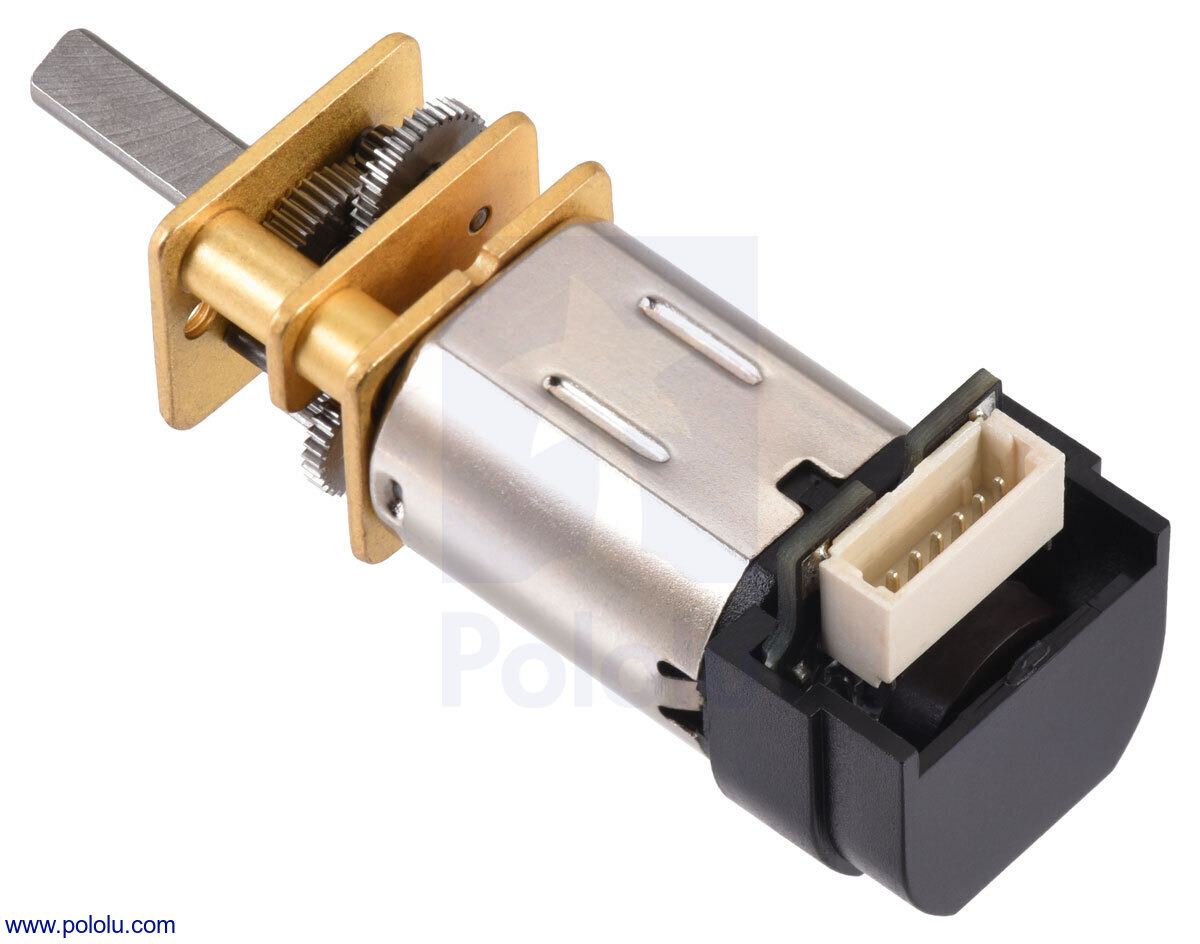
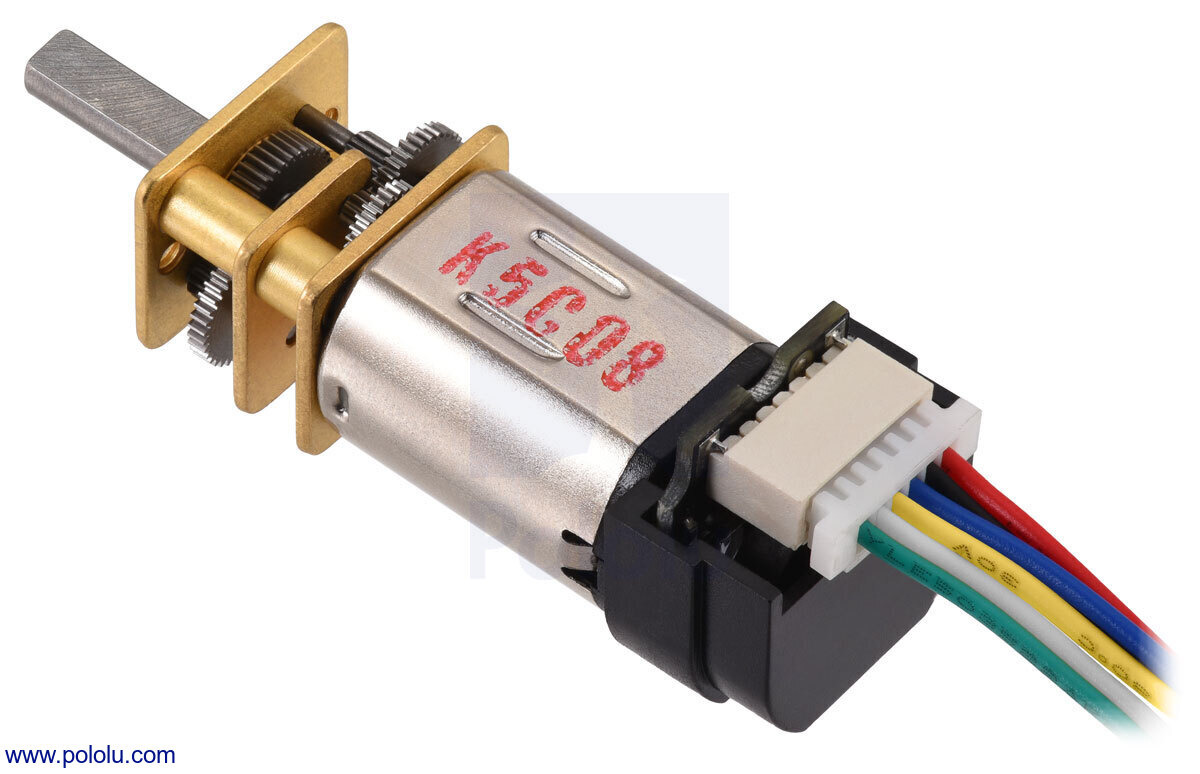
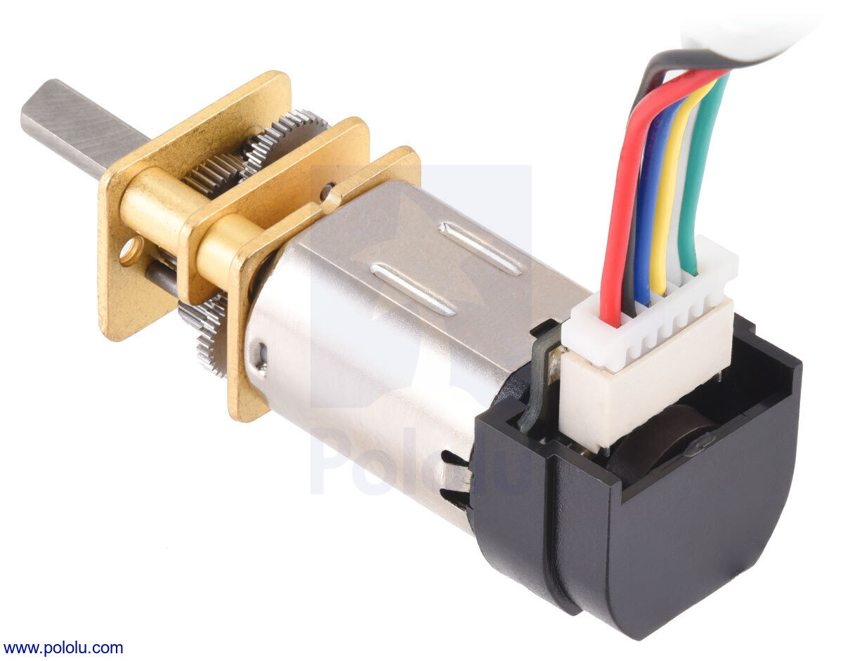
Our Micro Metal Gearmotors are now available with integrated quadrature encoders! These are the same top-entry and side-entry encoders that were previously only available separately, and now you can get them preassembled on the gearmotors and covered by a snap-on plastic cap. On the assembled units, the two available styles are denoted as “Back Connector”, which has the connector oriented parallel to the motor, and “Side Connector”, which is perpendicular to the motor. These connectors work with our assortment of female 6-pin JST SH-style cables and 6-pin JST SH-style connector boards.
|
|
For detailed dimensions, specifications, and usage information, see the Micro Metal Gearmotor datasheet (5MB pdf).
With 65 different combinations of gearboxes and motors each now available with two encoder styles, that makes 130 new products in all, and it increases our total Micro Metal Gearmotor selection to 260 versions. We are still working on getting everything stocked up, but we manufacture these in house, so we can make some of any particular version quickly. If there is a version you want that is currently out of stock, you can backorder it and we should be able to make and ship it in a few days. (Please note that we are currently not stocking the 5:1 versions with encoders but we are able to make them by special request; please contact us if you are interested in placing a special order for those.) Here is a full list of all the available options now:
| Rated Voltage |
Stall Current |
No-Load Current |
No-Load Speed (RPM) |
Extrapolated Stall Torque |
Max Power (W) |
Approx Gear Ratio |
 No Encoder |
 w/ Extended Motor Shaft |
 w/ Encoder, Back Conn. |
 w/ Encoder, Side Conn. |
|
|---|---|---|---|---|---|---|---|---|---|---|---|
| (kg⋅cm) | (oz⋅in) | ||||||||||
| HPCB 12V (high-power, carbon brushes) |
|||||||||||
| 12 V | 0.75 A | 100 mA | 6800 | 0.09 | 1.3 | – | 5:1 | #3036 | #3047 | #5204 | #5205 |
| 80 mA | 3400 | 0.17 | 2.4 | 1.5 | 10:1 | #3037 | #3048 | #5206 | #5207 | ||
| 2200 | 0.25 | 3.5 | 1.4 | 15:1 | #4788 | #4789 | #5208 | #5209 | |||
| 1100 | 0.39 | 5.4 | 1.1 | 30:1 | #3038 | #3049 | #5210 | #5211 | |||
| 650 | 0.67 | 9.3 | 1.1 | 50:1 | #3039 | #3050 | #5212 | #5213 | |||
| 450 | 1.0 | 14 | 1.1 | 75:1 | #3040 | #3051 | #5214 | #5215 | |||
| 330 | 1.3 | 18 | 1.1 | 100:1 | #3041 | #3052 | #5216 | #5217 | |||
| 220 | 1.8 | 25 | 1.0 | 150:1 | #3042 | #3053 | #5218 | #5219 | |||
| 160 | 2.5 | 35 | 1.0 | 210:1 | #3043 | #3054 | #5220 | #5221 | |||
| 130 | 3.0 | 42 | 1.1 | 250:1 | #3044 | #3055 | #5222 | #5223 | |||
| 110 | 3.3 | 46 | 1.0 | 298:1 | #3045 | #3056 | #5224 | #5225 | |||
| 85 | 5.0 | 69 | 1.1 | 380:1 | #4798 | #4799 | #5226 | #5227 | |||
| 35 | 10 | 140 | – | 1000:1 | #3046 | #3057 | #5228 | #5229 | |||
| Rated Voltage |
Stall Current |
No-Load Current |
No-Load Speed (RPM) |
Extrapolated Stall Torque |
Max Power (W) |
Approx Gear Ratio |
No Encoder | w/ Extended Motor Shaft |
w/ Encoder, Back Conn. |
w/ Encoder, Side Conn. |
|
| (kg⋅cm) | (oz⋅in) | ||||||||||
| HPCB 6V (high-power, carbon brushes) |
|||||||||||
| 6 V | 1.5 A | 170 mA | 6500 | 0.09 | 1.3 | – | 5:1 | #3060 | #3082 | #5178 | #5179 |
| 150 mA | 3300 | 0.17 | 2.4 | 1.3 | 10:1 | #3061 | #3071 | #5180 | #5181 | ||
| 2100 | 0.25 | 3.5 | 1.3 | 15:1 | #4786 | #4787 | #5182 | #5183 | |||
| 1100 | 0.45 | 6.2 | 1.2 | 30:1 | #3062 | #3072 | #5184 | #5185 | |||
| 650 | 0.74 | 10 | 1.2 | 50:1 | #3063 | #3073 | #5186 | #5187 | |||
| 430 | 1.1 | 15 | 1.3 | 75:1 | #3064 | #3074 | #5188 | #5189 | |||
| 330 | 1.6 | 22 | 1.3 | 100:1 | #3065 | #3075 | #5190 | #5191 | |||
| 220 | 2.0 | 28 | 1.1 | 150:1 | #3066 | #3076 | #5192 | #5193 | |||
| 160 | 2.8 | 39 | 1.1 | 210:1 | #3067 | #3077 | #5194 | #5195 | |||
| 130 | 3.2 | 44 | 1.1 | 250:1 | #3068 | #3078 | #5196 | #5197 | |||
| 110 | 3.4 | 47 | 1.0 | 298:1 | #3069 | #3079 | #5198 | #5199 | |||
| 85 | 5.0 | 69 | 1.1 | 380:1 | #4796 | #4797 | #5200 | #5201 | |||
| 33 | 11 | 150 | – | 1000:1 | #3070 | #3080 | #5202 | #5203 | |||
| Rated Voltage |
Stall Current |
No-Load Current |
No-Load Speed (RPM) |
Extrapolated Stall Torque |
Max Power (W) |
Approx Gear Ratio |
No Encoder | w/ Extended Motor Shaft |
w/ Encoder, Back Conn. |
w/ Encoder, Side Conn. |
|
| (kg⋅cm) | (oz⋅in) | ||||||||||
| HP 6V (high-power) |
|||||||||||
| 6 V | 1.6 A | 120 mA | 6100 | 0.11 | 1.5 | – | 5:1 | #1000 | #2210 | #5152 | #5153 |
| 100 mA | 3100 | 0.22 | 3.0 | 1.6 | 10:1 | #999 | #2211 | #5154 | #5155 | ||
| 2000 | 0.30 | 4.2 | 1.5 | 15:1 | #4784 | #4785 | #5156 | #5157 | |||
| 1000 | 0.57 | 7.9 | 1.5 | 30:1 | #1093 | #2212 | #5158 | #5159 | |||
| 590 | 0.86 | 12 | 1.3 | 50:1 | #998 | #2213 | #5160 | #5161 | |||
| 410 | 1.3 | 18 | 1.4 | 75:1 | #2361 | #2215 | #5162 | #5163 | |||
| 310 | 1.7 | 24 | 1.3 | 100:1 | #1101 | #2214 | #5164 | #5165 | |||
| 210 | 2.4 | 33 | 1.2 | 150:1 | #997 | #2386 | #5166 | #5167 | |||
| 150 | 3.0 | 42 | 1.1 | 210:1 | #996 | #2216 | #5168 | #5169 | |||
| 120 | 3.4 | 47 | 1.1 | 250:1 | #995 | #2217 | #5170 | #5171 | |||
| 100 | 4.0 | 56 | 1.1 | 298:1 | #994 | #2218 | #5172 | #5173 | |||
| 84 | 5.5 | 76 | 1.1 | 380:1 | #4794 | #4795 | #5174 | #5175 | |||
| 31 | 12 | 170 | – | 1000:1 | #1595 | #2373 | #5176 | #5177 | |||
| Rated Voltage |
Stall Current |
No-Load Current |
No-Load Speed (RPM) |
Extrapolated Stall Torque |
Max Power (W) |
Approx Gear Ratio |
No Encoder | w/ Extended Motor Shaft |
w/ Encoder, Back Conn. |
w/ Encoder, Side Conn. |
|
| (kg⋅cm) | (oz⋅in) | ||||||||||
| MP 6V (medium-power) |
|||||||||||
| 6 V | 0.67 A | 80 mA | 4400 | 0.06 | 0.8 | – | 5:1 | #2362 | #2376 | #5126 | #5127 |
| 70 mA | 2200 | 0.11 | 1.5 | – | 10:1 | #2363 | #2377 | #5128 | #5129 | ||
| 1400 | 0.20 | 2.8 | 0.70 | 15:1 | #4782 | #4783 | #5130 | #5131 | |||
| 720 | 0.33 | 4.6 | 0.57 | 30:1 | #2364 | #2378 | #5132 | #5133 | |||
| 420 | 0.54 | 7.5 | 0.55 | 50:1 | #2365 | #2379 | #5134 | #5135 | |||
| 290 | 0.78 | 11 | 0.54 | 75:1 | #2366 | #2380 | #5136 | #5137 | |||
| 220 | 0.94 | 13 | 0.50 | 100:1 | #2367 | #2381 | #5138 | #5139 | |||
| 150 | 1.3 | 18 | 0.48 | 150:1 | #2368 | #2382 | #5140 | #5141 | |||
| 100 | 1.7 | 24 | 0.46 | 210:1 | #2369 | #2383 | #5142 | #5143 | |||
| 88 | 2.2 | 31 | 0.48 | 250:1 | #2370 | #2384 | #5144 | #5145 | |||
| 73 | 2.4 | 33 | 0.44 | 298:1 | #2371 | #2385 | #5146 | #5147 | |||
| 57 | 3.6 | 50 | 0.53 | 380:1 | #4792 | #4793 | #5148 | #5149 | |||
| 22 | 6.7 | 93 | – | 1000:1 | #2372 | #3059 | #5150 | #5151 | |||
| Rated Voltage |
Stall Current |
No-Load Current |
No-Load Speed (RPM) |
Extrapolated Stall Torque |
Max Power (W) |
Approx Gear Ratio |
No Encoder | w/ Extended Motor Shaft |
w/ Encoder, Back Conn. |
w/ Encoder, Side Conn. |
|
| (kg⋅cm) | (oz⋅in) | ||||||||||
| LP 6V (low-power) |
|||||||||||
| 6 V | 0.36 A | 50 mA | 2500 | 0.05 | 0.7 | – | 5:1 | #1100 | #2200 | #5100 | #5101 |
| 40 mA | 1300 | 0.10 | 1.4 | – | 10:1 | #1099 | #2201 | #5102 | #5103 | ||
| 860 | 0.17 | 2.4 | 0.37 | 15:1 | #4780 | #4781 | #5104 | #5105 | |||
| 450 | 0.29 | 4.0 | 0.31 | 30:1 | #993 | #2202 | #5106 | #5107 | |||
| 270 | 0.44 | 6.1 | 0.29 | 50:1 | #1098 | #2203 | #5108 | #5109 | |||
| 180 | 0.64 | 8.9 | 0.29 | 75:1 | #2360 | #2209 | #5110 | #5111 | |||
| 130 | 0.74 | 10 | 0.25 | 100:1 | #992 | #2204 | #5112 | #5113 | |||
| 90 | 1.1 | 15 | 0.25 | 150:1 | #1097 | #2205 | #5114 | #5115 | |||
| 65 | 1.6 | 22 | 0.25 | 210:1 | #1096 | #2206 | #5116 | #5117 | |||
| 54 | 1.7 | 24 | 0.23 | 250:1 | #1095 | #2207 | #5118 | #5119 | |||
| 45 | 2.0 | 28 | 0.22 | 298:1 | #1094 | #2208 | #5120 | #5121 | |||
| 36 | 2.9 | 40 | 0.27 | 380:1 | #4790 | #4791 | #5122 | #5123 | |||
| 13 | 5.5 | 76 | – | 1000:1 | #1596 | #3058 | #5124 | #5125 | |||
Note: Stalling or overloading gearmotors can greatly decrease their lifetimes and even result in immediate damage. The recommended upper limit for instantaneous torque is 2.5 kg⋅cm (35 oz⋅in) for the 380:1 and 1000:1 gearboxes, and 2 kg⋅cm (25 oz⋅in) for all the other gear ratios; we strongly advise keeping applied loads well under this limit. Stalls can also result in rapid (potentially on the order of seconds) thermal damage to the motor windings and brushes, especially for the versions that use high-power (HP and HPCB) motors; a general recommendation for brushed DC motor operation is 25% or less of the stall current.
Related products


New products: D30V3x series step-down voltage regulators
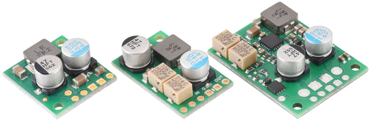 |
We’re pleased to introduce the D30V3x line of step-down voltage regulators, our favorite new buck regulators for applications that need up to a few amps from input voltages up to 45 V. They can deliver between 1 A and 4 A of output current, depending on the input and output voltages, with very low dropout voltages. They also feature a power-good output for identifying when the output voltage is not being maintained, an enable pin with a precise threshold for turning off the regulator, and a soft-start feature that limits in-rush current and gradually ramps the output voltage on startup. The regulators include protections against reverse voltage (up to 40 V), input under-voltage, over-temperature, over-current, and short circuits.
 |
 |
 |
The D30V3x line consists of the following three families:
- The D30V30Fx regulators are compact, fixed-output versions available with output voltages from 3.3 V to 15 V.
- The D30V30MAx regulators are compact, double-sided adjustable versions, with a precision-adjustable output voltage from 4.2 V to 15 V and an optional adjustable low-voltage cutoff.
- The D30V33MAx regulators are larger adjustable versions with holes for terminal blocks and slightly higher maximum output current. These also have a precision-adjustable 4.2 V to 15 V output and an optional adjustable low-voltage cutoff.
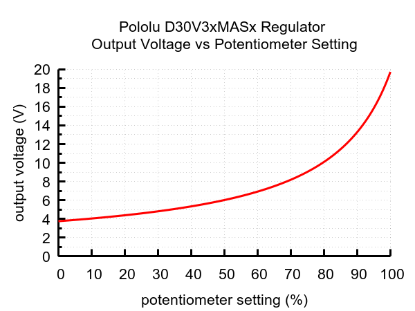 |
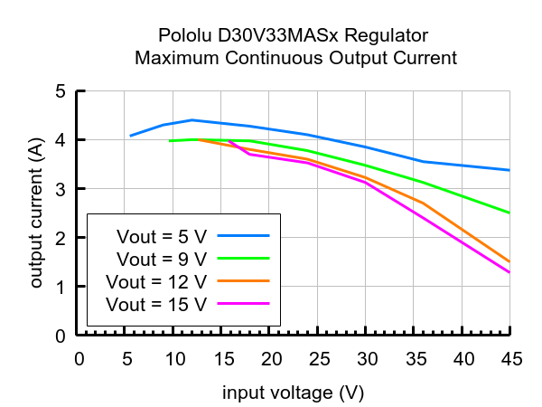
Output voltage settings for the 4.2-15V Fine-Adjust Step-Down Voltage Regulator D30V3xMASx. |
|---|
We’ve actually had the fixed-voltage versions available for a few months already, but we’ve just expanded the range with the release of the adjustable versions, which have multi-turn potentiometers for precisely setting the output voltage and/or low voltage cutoff. The following table shows all of the members of the D30V3x family:
| Regulator | Output voltage | Typical max output current1 |
Input voltage2 | Adjustable low-voltage cutoff |
Size | |
|---|---|---|---|---|---|---|
| #4891: D30V30F3 | 3.3 V | 3.7 A | 3.3 V – 45 V | 0.7″ × 0.8″ | ||
| #4892: D30V30F5 | 5 V | 3.4 A | 5 V – 45 V | |||
| #4893: D30V30F6 | 6 V | 3.3 A | 6 V – 45 V | |||
| #4894: D30V30F7 | 7.5 V | 3 A | 7.5 V – 45 V | |||
| #4895: D30V30F9 | 9 V | 2.9 A | 9 V – 45 V | |||
| #4896: D30V30F12 | 12 V | 2.8 A | 12 V – 45 V | |||
| #4897: D30V30F15 | 15 V | 2.7 A | 15 V – 45 V | |||
| #4874: D30V30MASCMA | 4.2 V – 15 V | 3 A | 4.2 V – 45 V | 0.6″ × 1.0″ | ||
| #4875: D30V30MAS | ||||||
| #4854: D30V33MASCMA | 4.2 V – 15 V | 3.3 A | 4.2 V – 45 V | 0.9″ × 1.2″ | ||
| #4855: D30V33MAS | ||||||
| 1At 30 V in. Actual achievable continuous output current is a function of input and output voltages and is limited by thermal dissipation. | ||||||
| 2Operating voltage must be higher than the set output voltage and is subject to dropout voltage considerations. | ||||||
New product: VL53L8CX Time-of-Flight 8×8-Zone Distance Sensor Carrier
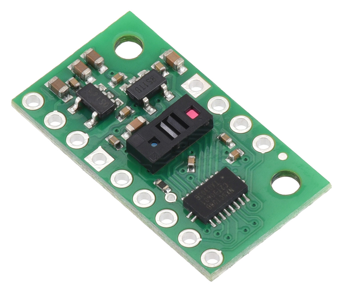 |
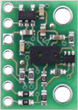
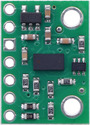
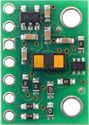
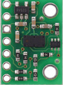
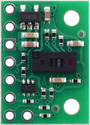
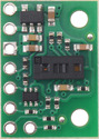
I’m excited to announce the release of our new VL53L8CX Time-of-Flight 8×8-Zone Distance Sensor Carrier, a multi-zone rangefinder based on ST’s latest VL53L8CX FightSense distance sensor. It uses time-of-flight (TOF) readings of infrared laser light to precisely measure distances of multiple targets across a grid of multiple zones, allowing you to generate a depth map with up to 8×8 resolution and 4 m range. Relative to older similar sensors, such as the VL53L5CX, the VL53L8CX also offers improved performance in ambient light and adds an SPI interface that can significantly speed up initialization and data acquisition. Since it has the same FOV and multi-zone capability, you can think of the VL53L8CX as basically an upgraded version of the VL53L5CX.
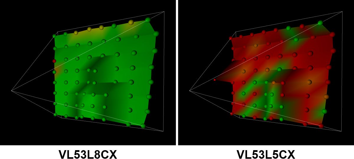 |
Visualization of VL53L8CX and VL53L5CX sensing a person standing against a wall about 2.7 m away. The VL53L8CX gives more accurate measurements with higher confidence (indicated with green). |
|---|
Compared to sensors that only give a 1D measurement, the VL53L8CX does demand more from a microcontroller to support its operation as a 3D lidar. Initializing the sensor through I²C or SPI and processing its data requires a lot of RAM and program memory, so it is not practical to use the VL53L8CX with most 8-bit MCUs like the Arduino Uno. We found that the Raspberry Pi Pico’s RP2040 microcontroller worked well for interfacing with the VL53L8CX, and other similarly powerful 32-bit controllers like an ESP32 should also work.
With the release of this module, we now have seven pin-compatible carriers for ST’s various FlightSense time-of-flight sensors:
 VL6180X carrier |
 VL53L0X carrier |
 VL53L1X carrier |
 VL53L3CX carrier |
 VL53L5CX carrier |
 VL53L7CX carrier |
 VL53L8CX carrier |
|
|---|---|---|---|---|---|---|---|
| Maximum range:(1) | 60 cm | 200 cm | 400 cm | 500 cm | 400 cm | 350 cm | 400 cm |
| Minimum range: | ~1 cm | ~3 cm | 4 cm | 1 cm | 2 cm | 2 cm | 2 cm |
| Field of view: | 25° | 25° | 15° to 27° diagonal, programmable |
25° | 65° diagonal, up to 8×8 zones |
90° diagonal, up to 8×8 zones |
65° diagonal, up to 8×8 zones |
| Other features: | ambient light sensing, low memory footprint(2) |
low memory footprint(2) | low memory footprint(2) | multi-target detection | multi-target detection | multi-target detection | multi-target detection, improved performance in ambient light |
| Maximum update rate:(1) | ~150 Hz | 50 Hz | 100 Hz | 125 Hz | 60 Hz | 60 Hz | 60 Hz |
| Operating voltage range: | 2.6 V to 5.5 V | 2.5 V to 5.5 V | 3.2 V to 5.5 V | ||||
| Regulator voltage: | 2.8 V | 3.3 V | 1.8 V and 3.3 V | ||||
| Typical active-ranging supply current: |
25 mA | 20 mA | 20 mA | 20 mA | 100 mA | 100 mA | 100 mA |
| Peak supply current: | 40 mA | 40 mA | 40 mA | 40 mA | 150 mA | 150 mA | 150 mA |
| Interface: | I²C | I²C, SPI | |||||
| Dimensions: | 0.5″ × 0.7″ | 0.5″ × 0.9″ | |||||
| 1-piece price: | $18.95 | $19.95 | $22.95 | $19.95 | $19.95 | $19.95 | $24.95 |
| 1 Effective range and update rate depend on configuration, target, and environment. 2 Suitable for use with typical 8-bit MCUs. |
|||||||
Related products

We now offer UV printing and more metal laser cutting capabilities!
 |
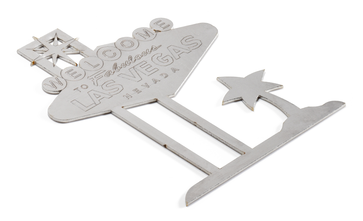
I’m excited to share some exciting improvements to our Custom Laser Cutting Service: a greatly expanded range of metal cutting capabilities and UV printing!
Metal laser cutting
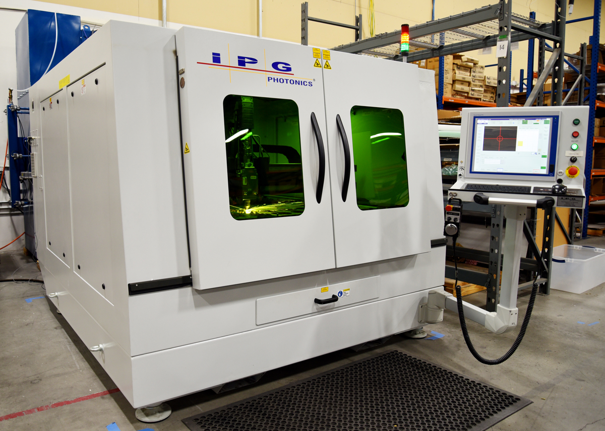
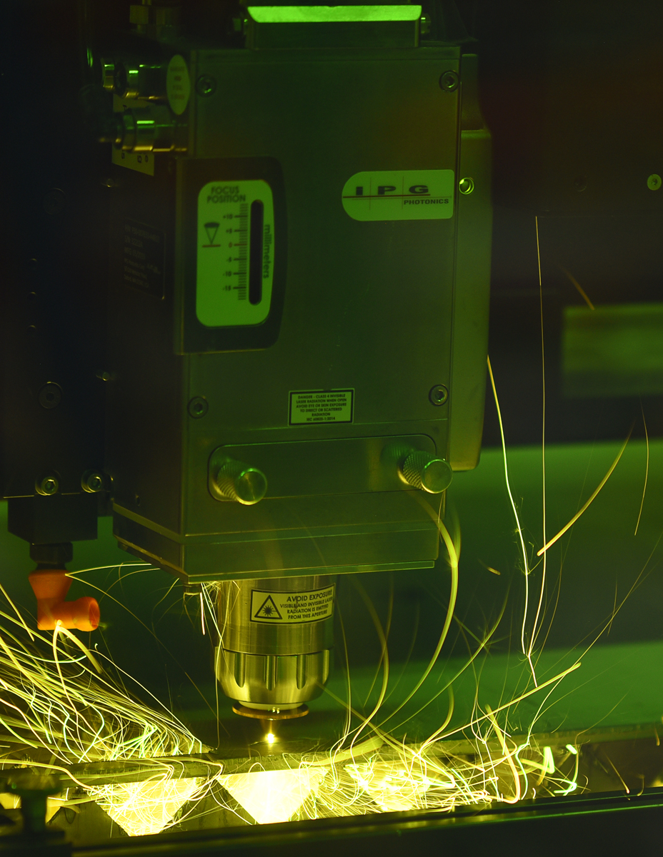
The last time we made a blog post about our laser cutting capabilities (over six years ago now), our most powerful machine was a 400 W CO2 laser cutter that could cut materials including plastics and woods up to 1″ (25.4 mm) thick, as well as steel up to 0.060″ (1.5 mm) thick. But we still weren’t satisfied with our metal cutting capabilities, so in the time since then, we have added an IPG Photonics LaserCube with a 3000 W fiber laser. The LaserCube is specifically designed to cut metals, enabling us to work with a wider variety of metals in thicknesses up to 1/4″ (6.35 mm).
|
|
Jan briefly mentioned the LaserCube in a blog post back in March 2020 just after we finished installing it—and right as the world was locking down in response to the COVID-19 pandemic. With the disruptions first from pandemic and then from the subsequent global parts shortages, almost all of our efforts went into keeping daily operations going, and developing new processes for fundamentally new equipment like the LaserCube got put on the back burner. Fortunately, things have been gradually getting back to normal and we are now ready to officially announce the new metal cutting capabilities the LaserCube enables!
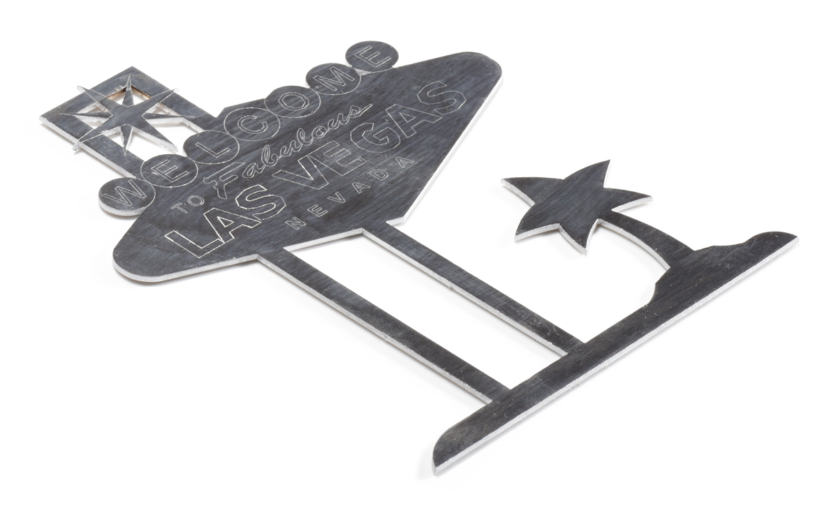
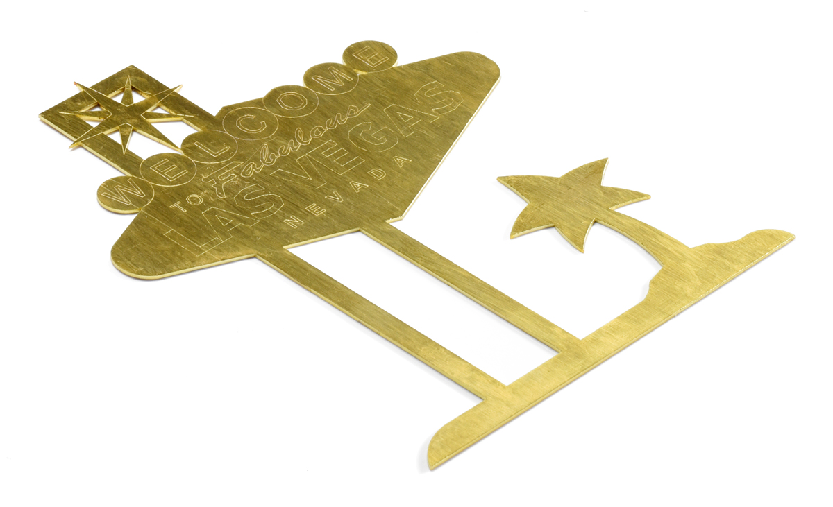
We can now cut:
- Steel up to 1/4″ (6.35 mm) thick
- Aluminum up to 1/4″ (6.35 mm) thick
- Brass up to 1/8″ (3.18 mm) thick
- Bronze up to 1/8″ (3.18 mm) thick
Correspondingly, we have added 5052 and 6061 aluminum to our regularly-stocked metals, joining 304 stainless steel and 1018 mild steel. We typically have sheets up to 24″ × 48″ (61 cm × 122 cm), but we can also order different metals/alloys or cut materials provided by customers up to 48″ × 48″. Additionally, since getting the LaserCube set up, we have started regularly using nitrogen (N2) as an assist gas, which helps cut parts with less discoloration and cleaner edges.
|
|
|
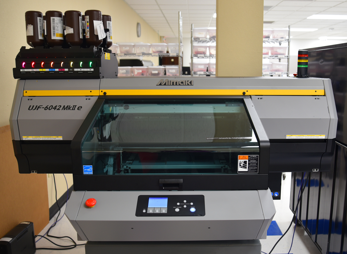
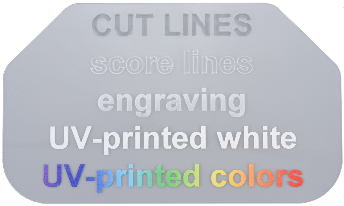
UV printing
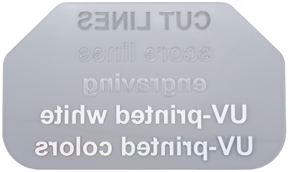
Our newest equipment is a Mimaki UJF-6042 MkII e UV printer, which lets us add vibrant and colorful labels, logos, photos, and artwork to your laser-cut parts. It can print with 1200 DPI resolution to an area up to 24″ × 16.5″ (61 cm × 42 cm), and the UV-cured ink adheres to many of the materials we laser cut, including plastics, wood, and yes, metal!
 |
 |
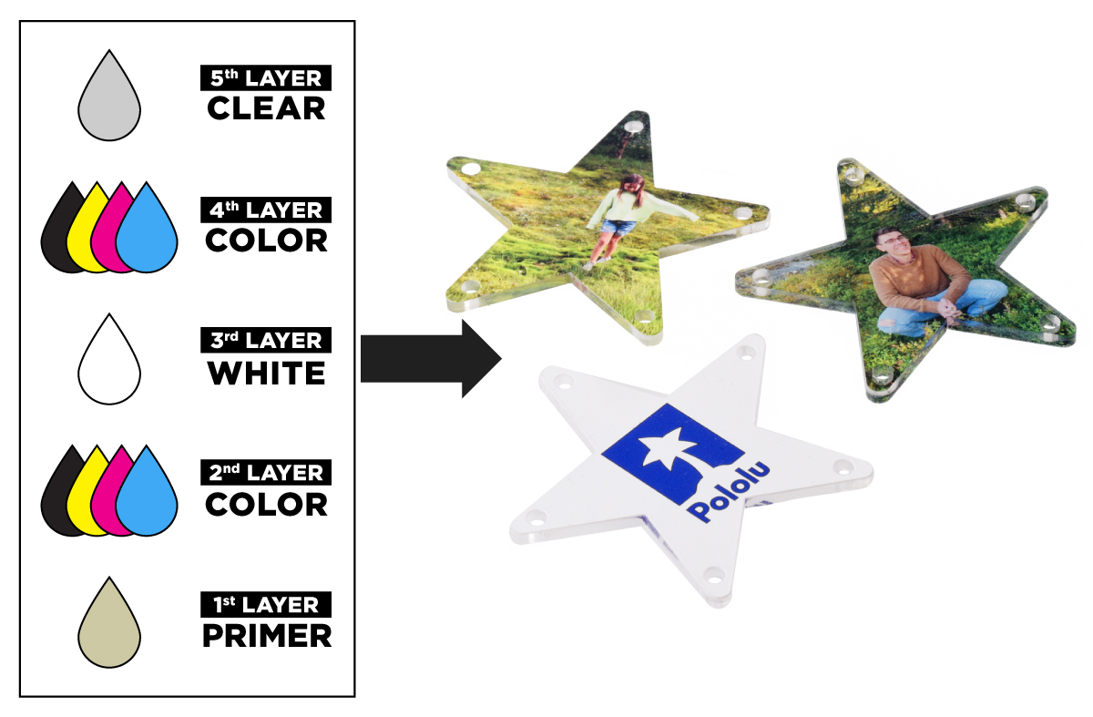
Our printer has inks for CMYK colors, plus a few special inks:
- White ink for printing vibrant colors on non-white materials
- Primer ink for helping the print better adhere to the material
- Clear ink for adding a layer of protection to the print
These different types of ink can be layered in various combinations for different effects.
|
|

|
|

We especially like printing on transparent materials, like clear acrylic, since there are so many ways you can print different layers of ink to create unique parts. For example, we can make opaque images visible from either side of the part by printing a layer of white sandwiched by two color layers like we did for these personalized Christmas tree ornaments.
 |
Laser-cut and UV-printed acrylic Christmas tree ornaments with two color layers for double-sided appearance. |
|---|
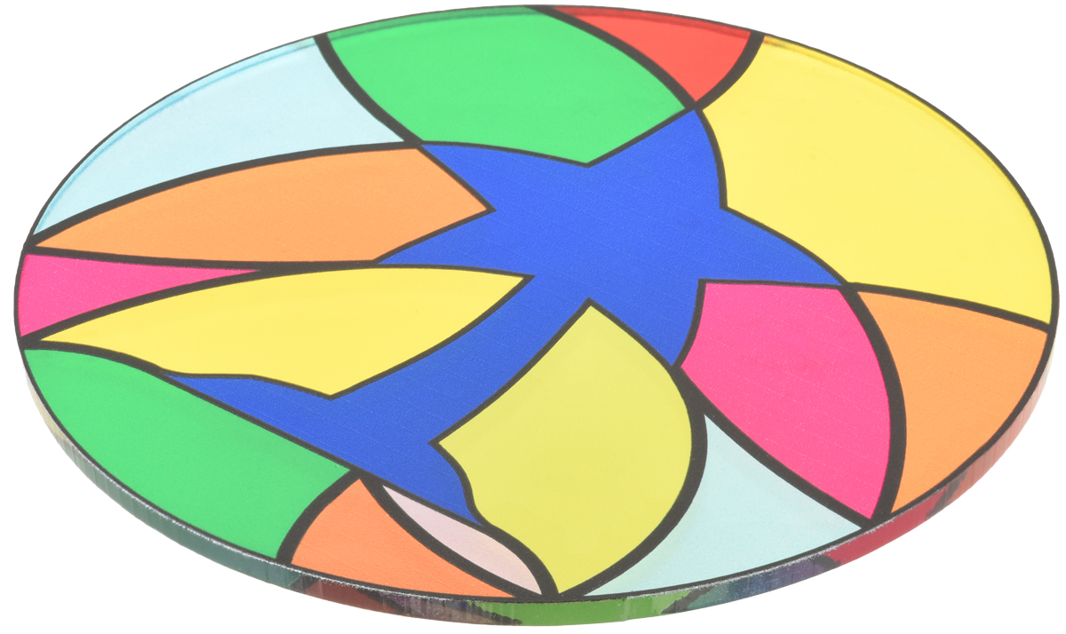
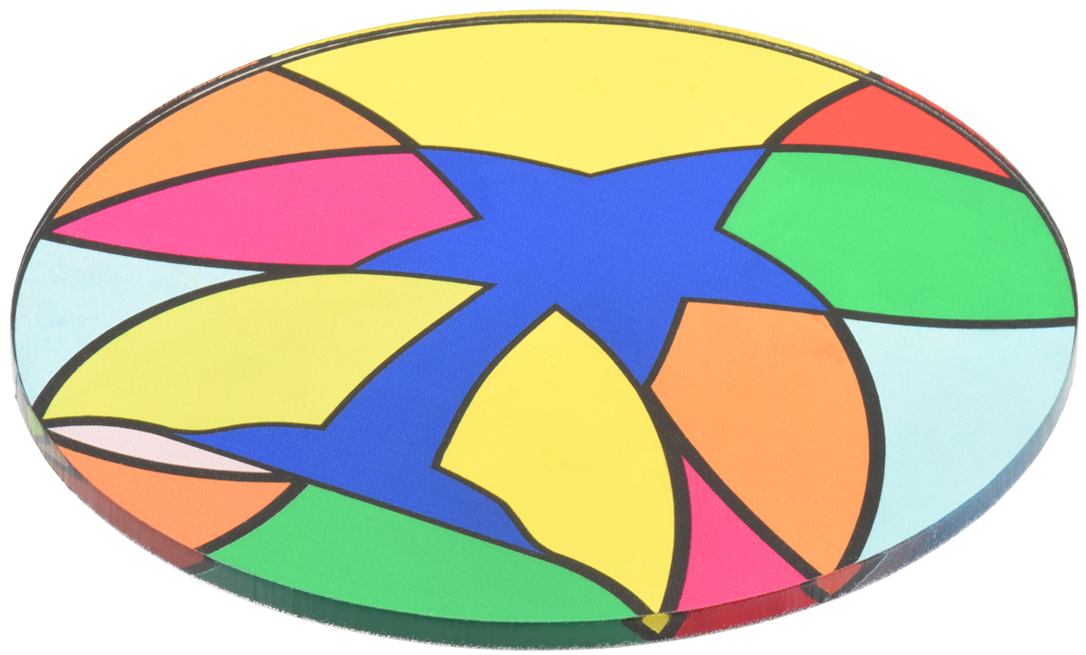
Alternatively, by strategically skipping the white layer in some areas of the print we can make transparent colorful parts that resemble stained glass.
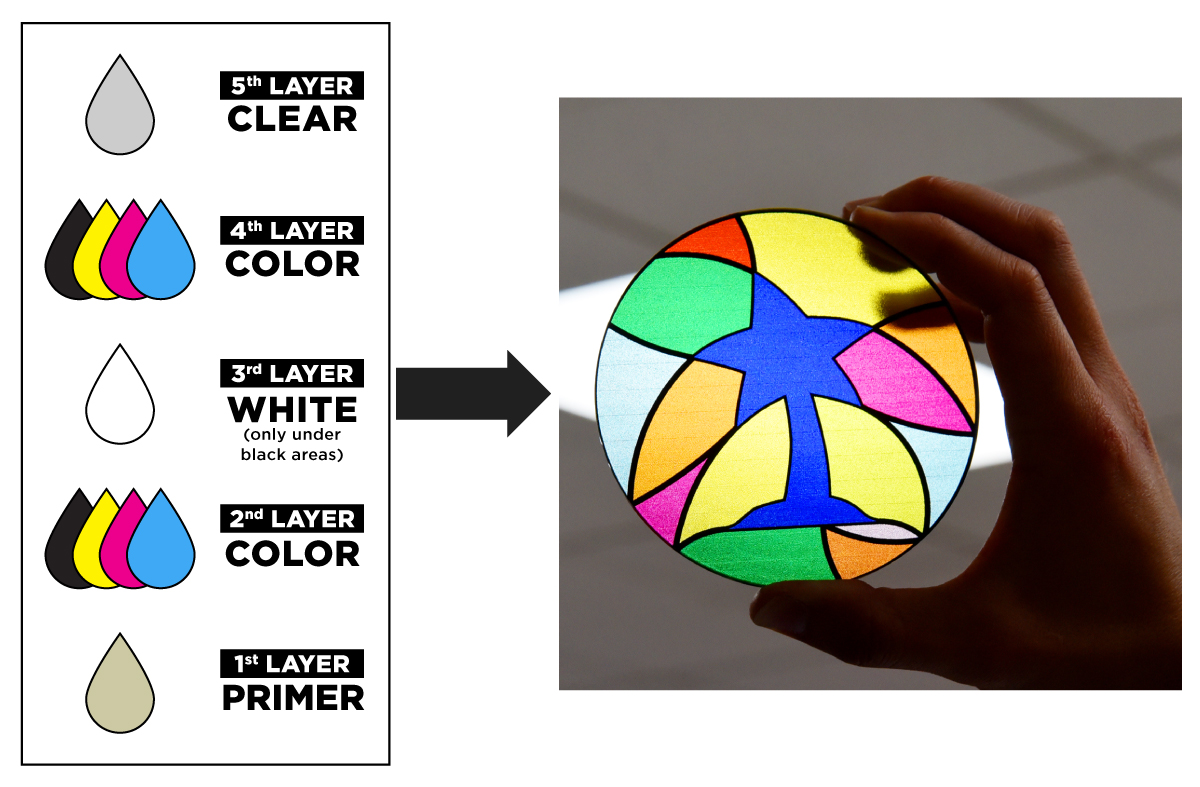 |
Laser-cut and UV-printed acrylic part with stained glass appearance. |
|---|
Getting a quote
You can submit a quote request for laser-cut metal parts, laser-cut parts with UV-printed artwork, or other types of laser-cut and engraved parts through our Custom Laser Cutting Service page. To get started, we recommend downloading one of our templates below, which already have the different layers set up.
 |
 |
 |
| CorelDRAW (340k cdr) | Adobe Illustrator (7MB ai) | Inkscape (457k svg) |
|---|
|
|
||||
|
|
Then, all you will need to do is add your artwork to the appropriate layer, save it, and submit a quote request!
For more detailed information about all of our capabilities and how to set up your files to make the process as smooth as possible, check out our Custom Laser Cutting Guide.
Share with us
We are excited to see what parts you design and how they get used in your projects! When you get your parts, consider posting some pictures in the Share Your Projects category of our forum. If you are still brainstorming ideas for your next project, our forum and blog posts tagged laser cutting
are a great places to find inspiration.
Related products

New product: Zumo 2040 Robot!
 |
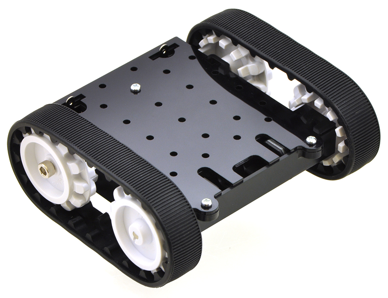
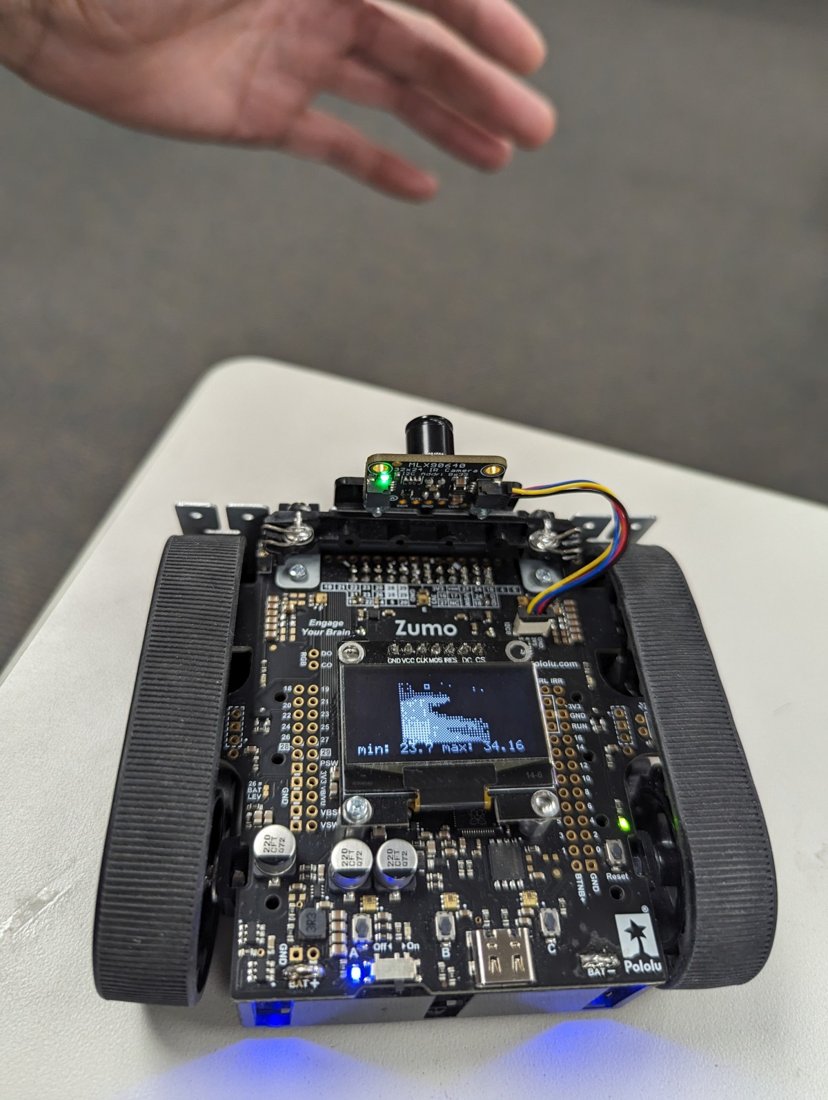
We’re happy to announce the release of the Zumo 2040, our newest RP2040-based robot built on our Zumo tracked chassis!
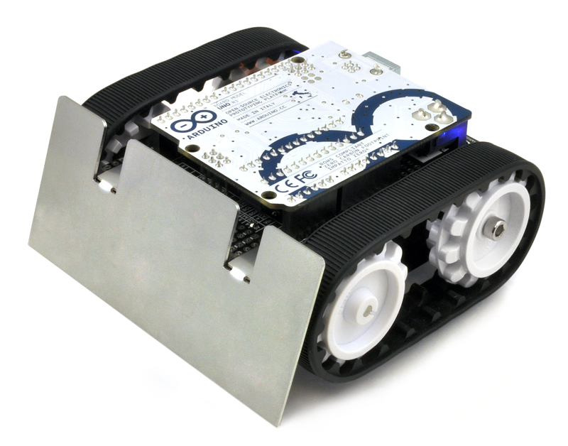
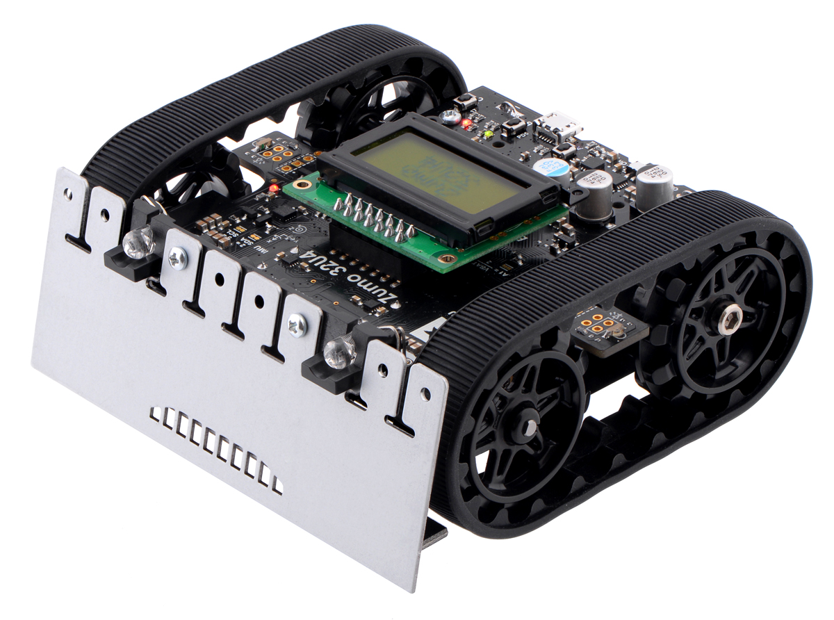
The Zumo started out as just that chassis: a simple mechanical base designed to be the foundation of a small tracked robot (and the right size for Mini-Sumo competitions). Later, we made the Zumo Robot Kit for Arduino that lets you build a complete robot with just the addition of an Arduino board, and a while after that, we released the Zumo 32U4 featuring a main board with an integrated AVR microcontroller.
|
|
|
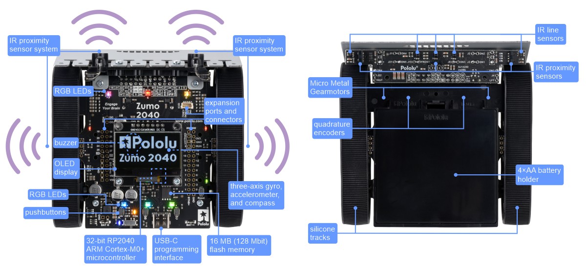
This new Zumo 2040 is the next big step in the evolution of the Zumo family, swapping out the Zumo 32U4’s 8-bit processor for a Raspberry Pi RP2040, a 32-bit dual-core Arm Cortex-M0+ microcontroller running at 125 MHz, along with 16 MB (128 Mbit) of flash memory. The more powerful processor (the same as on the Raspberry Pi Pico) enhances both what the Zumo can do and how you can work with it.
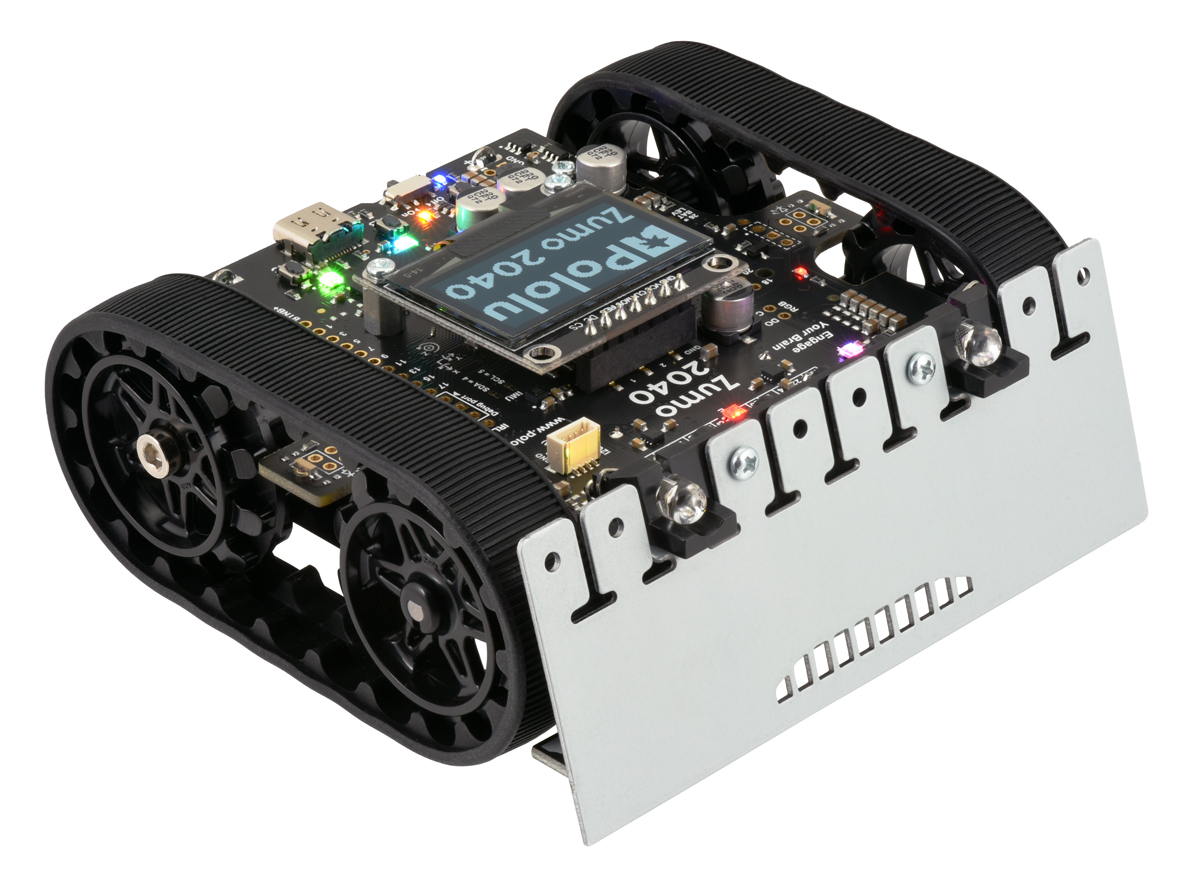 |
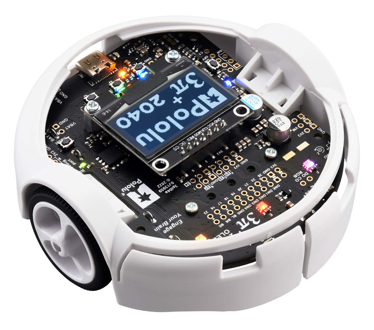
Assembled Zumo 2040 robot. |
|---|
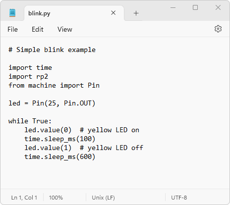
We particularly like how easy it is to get started programming the Zumo 2040 with MicroPython: just like with our 3pi+ 2040 Robot, you can simply connect the Zumo to a computer with a USB-C cable and start editing the included example Python programs with a text editor.
|
|

There are lots of pre-loaded examples that demonstrate how to use the various features on the Zumo 2040. Here’s one that uses the Zumo’s proximity sensors to locate and turn to face an opponent or other object (in this case, a 3pi+):
Although I summed up the history of the Zumo platform in a few major milestones above, that doesn’t really tell the whole story; there have been other smaller changes along the way (both accompanying and between the big releases) that have made it more of a continual process of improvement. For example, although the Zumo originally came with the white sprockets that you see in some of those pictures, we now ship the chassis and all of the robots and kits with black spoked sprockets that make assembly and disassembly easier (and look cooler). And a couple years ago, we revised the Zumo 32U4 with a better display (in the form of the Zumo 32U4 OLED), an upgrade that has carried over to this new Zumo.
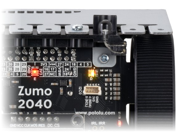
The Zumo 2040’s new I2C0 connector is one such smaller improvement, but it’s something that I hope will make a difference when it comes to expanding the robot with additional electronics. This is a 4-pin JST SH-compatible connector that provides access to the RP2040’s I2C0 bus, and it has a pinout compatible with Sparkfun’s Qwiic and Adafruit’s STEMMA QT connection systems, so that should make it easier to add I²C sensors and other devices to the Zumo.
|
|
The Zumo 2040 robot is available as a kit (with motors not included so you can select your own to customize performance) or as a fully assembled robot with your choice of 50:1, 75:1, or 100:1 motor options.
Related products


More Motoron motor controllers!
 |
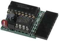
We recently added six new low-power variants to our Motoron line of basic serial motor controllers: four Mxx550 1- and 2-channel versions, as well as 3-channel versions for Arduino (M3S550) and Raspberry Pi (M3H550).
1- and 2-channel micro motor drivers
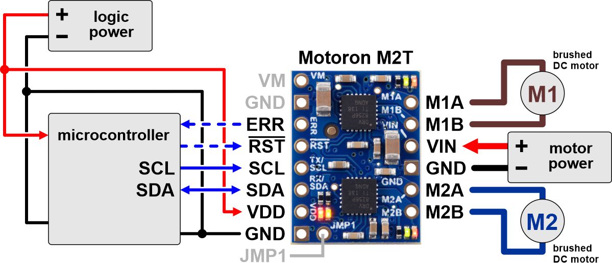
The new M1T550, M1U550, M2T550, and M2U550 are single- and dual-channel serial motor controllers in a micro footprint. With a maximum motor supply voltage of 22 V, the Mxx550 versions are a great way to control small motors powered by power supplies up to 12 V and battery packs up to 12 cells in series for alkaline, NiCd, and NiMH, or up to 4 cells in series for LiPo. These are lower-voltage, pin-compatible versions of the Mxx256 models we released earlier this year, which have a maximum motor voltage of 48 V and can deliver slightly more current but are otherwise almost identical.
Here is the full array of tiny Motoron options, including I²C and UART serial interface versions:
| Motoron motor controllers micro versions |
||||
 M1T550 M1U550 |
 M2T550 M2U550 |
 M1T256 M1U256 |
 M2T256 M2U256 |
|
|---|---|---|---|---|
| Control interface: | I²C or UART serial | |||
| Motor channels: | 1 (single) | 2 (dual) | 1 (single) | 2 (dual) |
| Minimum motor supply voltage: |
1.8 V | 4.5 V | ||
| Absolute max motor supply voltage: |
22 V | 48 V | ||
| Recommended max nominal battery voltage: |
16 V | 36 V | ||
| Max continuous current per channel: |
1.8 A | 1.6 A | 2.2 A | 1.8 A |
| Available versions with I²C: |
||||
| Available verions with UART serial: |
||||
| Price: | $12.49 – $14.49 | $15.95 – $17.95 | $16.95 – $18.95 | $23.95 – $25.95 |
3-channel motor drivers for Arduino and Raspberry Pi
We also released larger (but still small!), 3-channel versions in Arduino (M3S550) and Raspberry Pi (M3H550) compatible form factors. These again have a maximum motor supply voltage of 22 V and correspond to the 48 V max M3S256 and M3H256 versions we released in 2022. Here is the full line of larger Motoron serial motor controllers, including the even higher-power, dual-channel Motorons in full-size Arduino Shield or Raspberry Pi Hat form factors:
| Motoron motor controllers Arduino and Raspberry Pi form factor versions |
||||||
 M3S550  M3H550 |
 M3S256  M3H256 |
 M2S24v14  M2H24v14 |
 M2S24v16  M2H24v16 |
 M2S18v18  M2H18v18 |
 M2S18v20  M2H18v20 |
|
|---|---|---|---|---|---|---|
| Control interface: | I²C | |||||
| Motor channels: | 3 (triple) | 2 (dual) | ||||
| Minimum motor supply voltage: |
1.8 V | 4.5 V | 6.5 V | |||
| Absolute max motor supply voltage: |
22 V | 48 V | 40 V | 30 V | ||
| Recommended max nominal battery voltage: |
16 V | 36 V | 28 V | 18 V | ||
| Max continuous current per channel: |
1.7 A | 2 A | 14 A | 16 A | 18 A | 20 A |
| Available versions for Arduino: |
M3S550 | M3S256 | M2S24v14 | M2S24v16 | M2S18v18 | M2S18v20 |
| Available versions for Raspberry Pi: |
M3H550 | M3H256 | M2H24v14 | M2H24v16 | M2H18v18 | M2H18v20 |
| Price: | $20.95 – $30.95 | $34.95 – $44.95 | $59.95 – $69.95 | $115.95 – $124.95 | $59.95 – $69.96 | $95.95 – $104.95 |
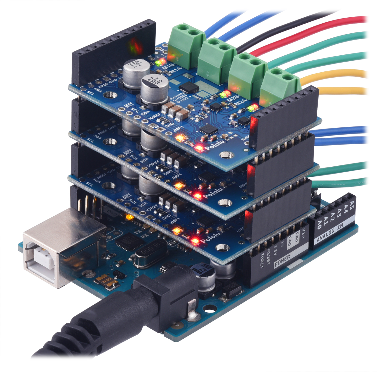
The great thing about the Motorons is that you can easily string together or stack multiple controllers, mixing and matching sizes to fit your application. For example, you could use one high-power dual motor version for drive motors on a mobile robot and then add a smaller 3-channel motor controller for additional actuators. This arrangement with three stacked Motorons on an Arduino Uno allows simple control of up to 9 motors:
 |
The common protocol between versions also makes it easy to change motor sizes and to reuse your code between projects. Want to make a bigger version of your first prototype? Just use a higher-power Motoron! Want to make a tiny robot next time? Use a tiny Motoron! Want to… you get the idea.
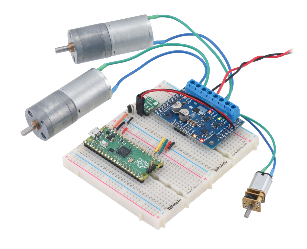
While the 3-channel boards are designed to stack on Arduinos or Raspberry Pis, they are also easy to use on breadboards:
 |
It may be easy to view the six new Mxx550 Motorons as just lower-voltage versions of the previously available Mxx256 Motorons, but I am especially excited about them because we are able to offer them at a very low price, extending the legacy of the Dual Serial Motor controllers that were among our first products over 20 years ago. We are launching the 2-channel M2T550 and M2U550 at just $15.95, a lower price than the original Dual Serial Motor controller from 2001 (without even adjusting for inflation!).
|
|
The chip shortages of the past several years have made it especially difficult to introduce new products and to keep their prices down, but things are finally seeming to get better on that front. You can see in the tables above that the higher-power 2-channel Motorons are much more expensive; those prices are still elevated because we are limited on some critical components we use there and in our other products. We should be able to manufacture plenty of the new Motorons without being constrained in a similar way.
Related products


New products: S13V25Fx step-up/step-down voltage regulators with fixed 3.3V to 15V output voltages
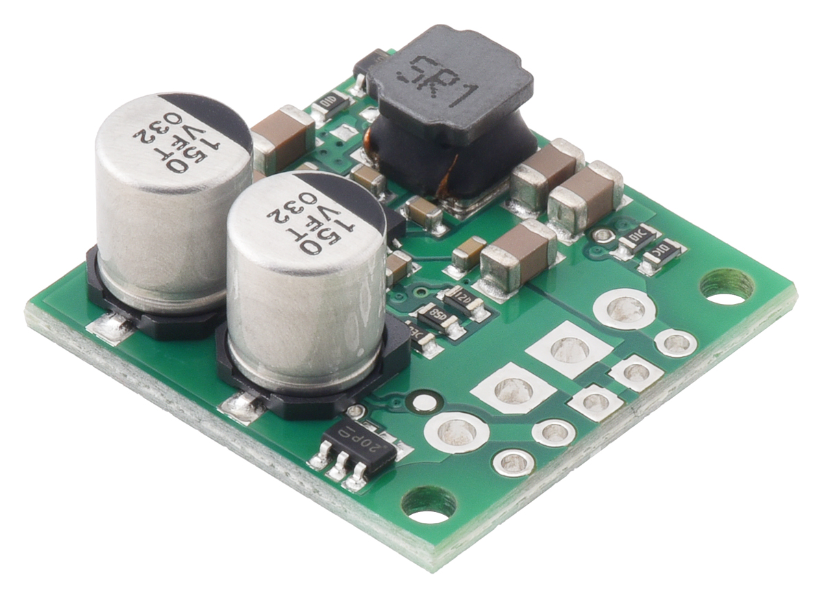 |
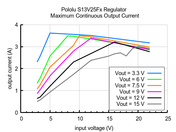
We have expanded our S13VxFx family of step-up/step-down voltage regulators to include options with a variety of output voltages from 3.3 V to 15 V. Like the original 5 V members of the family, these new S13V25Fx units take an input voltage from 2.8 V to 22 V and efficiently increase it or decrease it as necessary to produce the regulated output voltage. Even with their compact 0.9″ × 0.9″ size, they can deliver typical continuous output currents between 1 A and 3 A, making them our most powerful buck-boost converters. (That’s almost half the size of our previously highest-power step-up/step-down units, the S18V20Fx family, which are still being impacted by the global semiconductor shortages.) The graphs below show a more complete picture of the kinds of currents you can expect for different combinations of input and output voltages:
 |
These new S13V25Fx versions do not include a 5V option because we already have that in the S13V30F5. They are pin-compatible with that 5V module and have the same overall board dimensions, but please note that the tall components (i.e. electrolytic capacitors and inductor) are in different locations. Here is a comparison of the new S13V25Fx regulators (left) next to the S13V30F5 (right):
|
|

This table shows what the full family looks like now:
| Regulator | Output voltage | Typical max continuous output current | Input voltage range | Typical efficiency | Size | Price |
|---|---|---|---|---|---|---|
| #4083: S13V10F5 | 5 V | 1 A | 2.8 V – 22 V | 85% – 95% | 0.35″ × 0.475″ | $9.95 |
| #4084: S13V15F5 | 5 V | 1.5 A | $12.49 | |||
| #4085: S13V20F5 | 5 V | 2 A | $17.95 | |||
| #4082: S13V30F5 | 5 V | 3 A | 0.9″ × 0.9″ | $17.95 | ||
| #4980: S13V25F3 New! | 3.3 V | 2.5 A | $18.95 | |||
| #4981: S13V25F6 New! | 6 V | 2.5 A | $18.95 | |||
| #4982: S13V25F7 New! | 7.5 V | 2.5 A | $18.95 | |||
| #4983: S13V25F9 New! | 9 V | 2.5 A | $18.95 | |||
| #4984: S13V25F12 New! | 12 V | 2.5 A | $18.95 | |||
| #4985: S13V25F15 New! | 15 V | 2.5 A | $18.95 |
As a reminder, we manufacture these boards in-house at our Las Vegas facility, so we have the flexibility to make these regulators with custom fixed output voltages. If the voltage you need is not one of our standard options and you are interested in customization, please contact us.
Related products


3pi+ 2040 Robot full release with additional motor options
 |
We have transitioned from our initial early-adopter release to a full release of the 3pi+ 2040 Robot family! With the full release, we also have some additional motor options. Here’s the full lineup:
| 3pi+ 2040 Version | Products | Micro Metal Gearmotor | Top Speed | Comments |
|---|---|---|---|---|
| Standard Edition | assembled or kit | 30:1 MP 6V | 1.5 m/s | good combination of speed and controllability |
| Turtle Edition | assembled or kit | 75:1 LP 6V | 0.4 m/s | longest battery life, easiest to control, good for swarm robots or introductory robotics courses |
| Hyper Edition | assembled or kit | 15:1 HPCB 6V | ~4 m/s | very fast and difficult to control, easy to damage; only recommended for advanced users |
The Turtle Edition is a great choice for educational environments or anyplace else where slow, controlled speed is important. On the flip side, the Hyper Edition uses high-power motors with a low-gear-ratio gearbox to offer a LOT of speed, but this also means reduced control and a higher risk of the robot damaging itself, so we only recommend it for advanced users who want to push the limits of what this robot platform can do. We also make the 3pi+ 2040 control board and 3pi+ chassis available separately for those who would like to do something custom with one of our many other Micro Metal Gearmotor options.
To recap from our early adopter release announcement, this robot combines our 3pi+ chassis with the power of the Raspberry Pi RP2040 microcontroller, and it’s full of cool features:
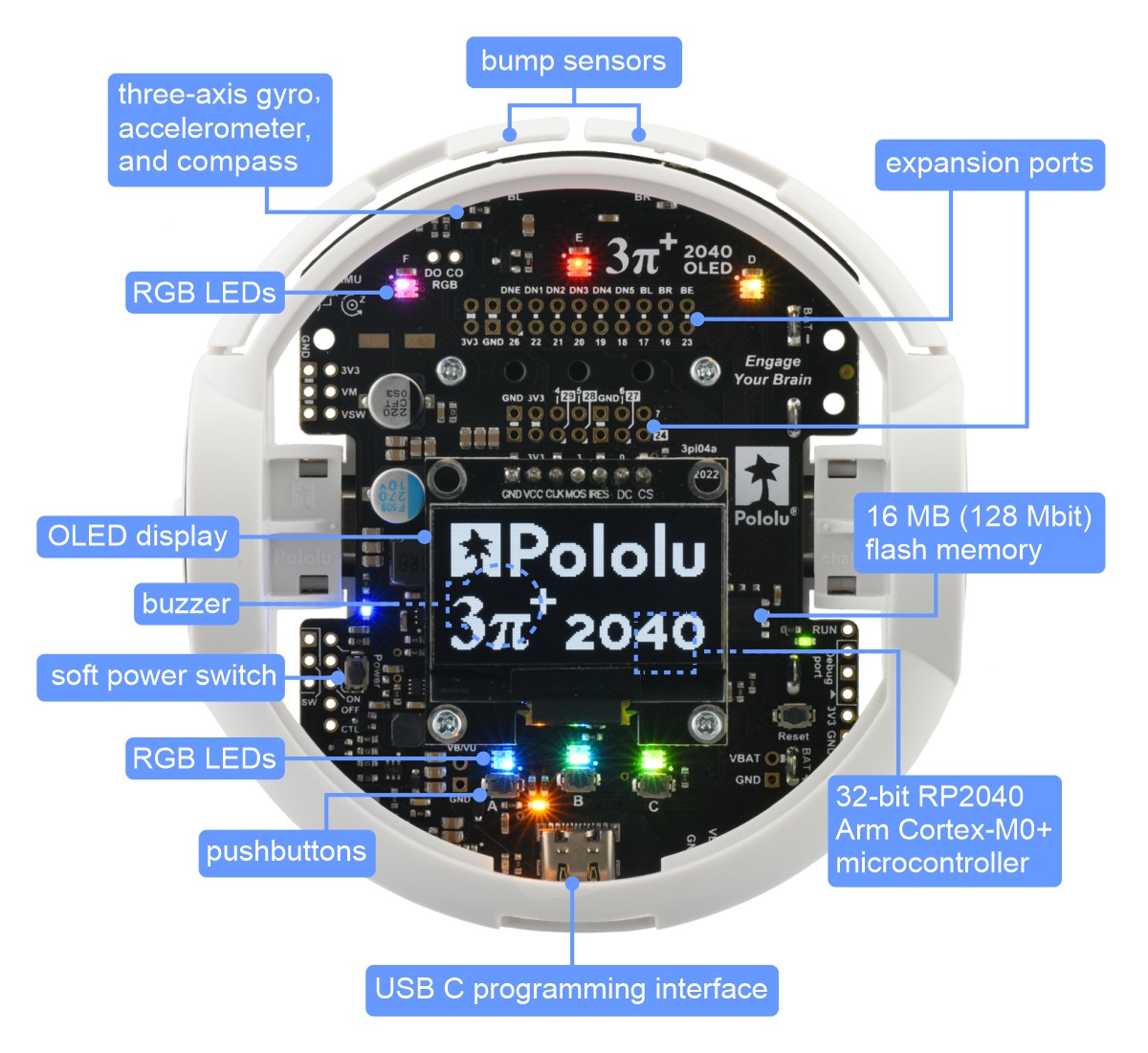 |
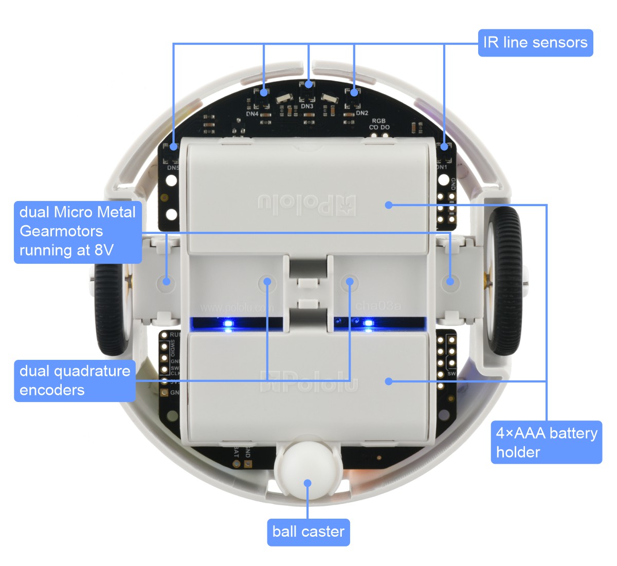 |
We have a comprehensive set of example Python programs to help get you started using all of these features, and we expect to continue adding more over time. Let us know if there’s something in particular you would want to see that is not already covered!
|
|

Related products


New product: LOCOSYS LC20031-V2 135-Channel Dual-Band GNSS Receiver Module
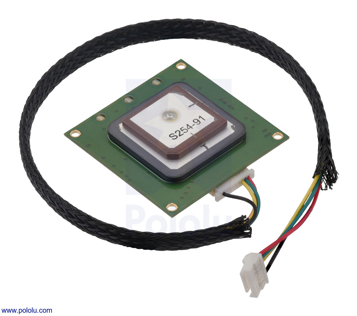 |
We’re now selling the LC20031-V2 GNSS receiver module from LOCOSYS. This module integrates a global navigation satellite system (GNSS) receiver with an on-board antenna, making it a complete solution for providing satellite-based position data (a “smart antenna”).
The LC20031-V2 outputs data at up to 10 Hz as NMEA sentences on a TTL-level serial port, or UART, and the module ships with a cable assembly that you can use to connect it to your project (either with a matching receptacle or by cutting off the connector to access the individual wire leads). A built-in rechargeable battery preserves system data while the module is inactive for rapid satellite acquisition on the next start-up.
Unlike GPS-only receivers such as the LS20031, the LC20031-V2 works with many different satellite systems. GPS, GLONASS, BeiDou, Galileo, and QZSS satellite signals are all supported, and the module can receive both L1 and L5 frequency band signals on up to 135 channels. This lets it achieve a typical position accuracy of 1.5 m CEP (circular error probable).
The GNSS Firebird software provided by LOCOSYS can be used to configure the LC20031-V2 and view its output. In this screenshot, you can easily see the different satellite systems that the receiver is tracking, represented by the different colors in the displays (GPS is blue, GLONASS is orange, Galileo is green, and BeiDou is red).
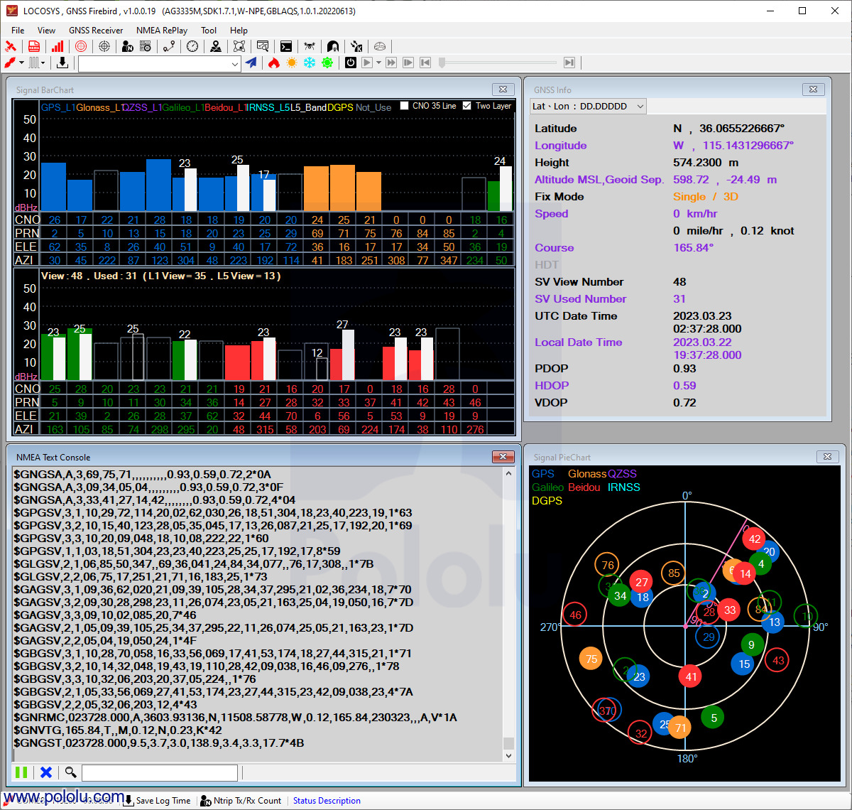 |
GNSS Firebird application showing data from an LC20031-V2 module inside Pololu’s offices. |
|---|
Related products


Home | Forum | Blog | Support | Ordering Information | Lists | Distributors | BIG Order Form | About | Contact
© 2001–2026 Pololu Corporation


