Pololu Blog » Posts tagged “new products” »
Posts tagged “new products” (Page 2)
You are currently viewing a selection of posts from the Pololu Blog. You can also view all the posts.
Popular tags: community projects new products raspberry pi arduino more…
New higher-power reverse voltage protector and ideal diode
 |
We are excited to announce the release of two new higher-power reverse voltage protectors that can handle up to around 25 A continuous while protecting your 4V–60V circuit from accidental destruction from reverse voltage:
- Reverse protection only – This version protects against reverse voltage while still allowing reverse current, making it suitable for applications such as battery-powered motor control where delivering energy back into the battery is desirable.
- Reverse protection with reverse current blocking – This version acts as an ideal diode, preventing current from flowing from output to input.
These boards feature larger 5×6mm MOSFETs with lower on-resistances and more than double the current carrying ability of the versions we released a few months ago, which makes the overall module larger (but still compact!):
 |
60V-max Pololu Reverse Voltage Protectors are available in 20A/25A (left) and 10A/12A (right) versions. |
|---|
With these new releases, we now have six total reverse protector options (with or without reverse current blocking in three different power levels):
| Reverse protection | Max current |
MOSFET on resistance |
Size | Price | Pololu Item # |
|---|---|---|---|---|---|
| Reverse voltage only | 10 A | < 10 mΩ | 0.3″×0.5″ | $3.29 | #5380 |
| 12 A | < 5 mΩ | $4.39 | #5381 | ||
| 25 A | < 1.5 mΩ | 0.435″×0.7″ | $7.95 | #5387 | |
| Reverse voltage and current (ideal diode) |
10 A | < 10 mΩ | 0.3″×0.5″ | $3.79 | #5382 |
| 12 A | < 5 mΩ | $4.95 | #5383 | ||
| 25 A | < 1.5 mΩ | 0.435″×0.7″ | $8.49 | #5389 | |
Introductory special discount! Use coupon code RVP25INTRO to get these new reverse voltage protectors for just $2.95!
Related products


New product: Isolated DC-DC Power Module, MIE1W0505BGLVH, 5V/3.3V, 200mA
 |
I am happy to introduce our first isolated power module, which we expect to kick off a new category of electrical isolation products (note that the many current sensors we carry also feature isolation from the sense side to the control side, but that isolation is part of their more dedicated current-sensing functionality). Many of our products are modules like motor controllers and regulator boards, and connecting several of them together in real-world settings can lead to unexpected problems from connecting all the grounds together. For example, your computer’s USB port can be a convenient source of 5 V, but the negative or ground side of that 5 V will likely be connected to the ground pin of the computer’s power cable and therefore to the ground side of everything else you have plugged into the wall. This can lead to unexpected problems as you build up your system, usually without thinking about your house being part of your circuit.
 |
There are more and more solutions for effectively moving power and signals without having an electrical connection, so we will be working on adding those into our more integrated products, and we will be adding to our isolation module portfolio to support our customers with the building blocks to make safer and more reliable systems themselves.
The module we are introducing today can provide galvanically isolated and regulated 5 V or 3.3 V power at up to 200 mA. It’s based on the MIE1W0505BGLVH from MPS, and it’s amazing how much is integrated into a chip like that, including a transformer to get the power from one side to the other without an electrical connection. Only a few passives are needed to support the IC, allowing our board to be small (0.3″ × 0.6″) and low-cost. It’s easy to use, too, with all the necessary information provided on the product page. The datasheet is available if you want more information, but you can use this module without knowing the details in there. (This is unlike what we call “carrier boards”, which require you to familiarize yourself with the chip.)
 |
Introductory special discount! Use coupon code 5384INTRO to get this new power module for just $2.75!
New product: High-Power Stepper Motor Driver 36v8
 |
 |
 |
We’re excited to announce the release of our new High-Power Stepper Motor Driver 36v8 for controlling large bipolar stepper motors. It operates over a wide 8 V to 50 V range and can deliver up to 8 A continuous per phase (11 A peak with sufficient additional cooling), making it our most powerful stepper motor driver by far. Here are some of its key features:
- Highly configurable through SPI interface
- Optional STEP/DIR control pins (stepping can also be controlled through SPI interface alone)
- Nine different step resolutions down to 256 microsteps: full-step, half-step, 1/4-step, 1/8-step, 1/16-step, 1/32-step, 1/64-step, 1/128-step, and 1/256-step
- Adjustable current control lets you set the maximum current output, enabling the use of voltages above your stepper motor’s rated voltage to achieve higher step rates
- Adaptive blanking time, adjustable decay times, and various current decay modes enable the creation of ultra-smooth motion profiles through the SPI interface
- Optional STALL output enables stall detection when microstepping
- Optional BEMF output enables more advanced control and stall detection algorithms based on the back EMF of the stepper motor
- Driver supports alternate operating mode for controlling two brushed DC motors with PWM inputs instead of one bipolar stepper motor with STEP/DIR inputs
- Inputs compatible with 1.8 V, 3.3 V, and 5 V logic
- Digital outputs are all open drain with pull-ups to externally supplied IOREF voltage for use with non-5V systems (IOREF can be connected to neighboring 5V OUT pin for use with 5V systems)
- Under-voltage lockout, over-current protection, short circuit protection, and reverse-voltage protection
- Arduino library and example sketches are available that provide basic functions for configuring and operating the driver
The 36v8 board has the same dimensions and pinout as the our older 36v4 version, so you can easily swap in this newer version to double the power to existing projects (or get the same power at lower temperatures).
Introductory special discount! Be one of the first to try out these new drivers and save $5 with coupon code HPSMD36V8INTRO!
Related products


New products: compact reverse voltage protection and ideal diodes
 |
We just released several small reverse voltage protection and ideal diode boards that can protect your projects from reverse voltage application. We have reverse-voltage protection built into many of our products, and we usually implement it using a P-channel MOSFET, like this:
 |
Reverse-voltage protection using a P-channel MOSFET. |
|---|
This approach is usually more efficient than just using a diode since the MOSFET has a lower voltage drop across it. However, P-channel MOSFETs have worse on-resistances than N-channel MOSFETs of similar prices and sizes. This has not mattered much for our lower-powered products, but that limitation is becoming more apparent as we are developing more products with maximum operating voltages over 40 V. The next common MOSFET voltage above 40 V is 60 V, and at that voltage and with currents above around 10 A, it starts becoming more size-efficient to use an N-channel MOSFET plus an extra chip to manage the additional complexities of controlling the N-channel MOSFET in this kind of application. This is how that circuit looks:
 |
Schematic diagram of the 60V Pololu Reverse Voltage Protectors (green PCBs). |
|---|
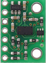
Since we are planning on using this approach on several new products, we decided to make standalone product versions as well. Here are how the first products look, using 3×3 mm MOSFETs:
 |
This lets us get up to about 10-12 amps continuous current and an operating range of 4-60 V, which is perfect for most of our products. We tried to make the board as small as possible, and for the input and output connections we are using a new slot approach that lets the boards work with standard 0.1" headers or connectors, 3.5 mm connectors, and 5 mm connectors.
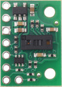
 |
Examples of various connectors that can be used with the Pololu 10A/12A Reverse Voltage Protectors (from left to right: 5mm terminal blocks, 3.5mm terminal blocks, 0.1″ headers). |
|---|
Texas Instruments offers two similar parts for the MOSFET controller. The LM74500 offers the same functionality as the simple P-channel MOSFET, allowing current to flow in both directions as long as the polarity is correct. This is useful for applications such as motor drivers where we want power to be able to flow back from the motor into the battery. There is also the LM74700 version, which makes the circuit function as an ideal diode, allowing current to flow in only one direction. We are offering our boards with both controller options and with two MOSFET options, for a total of four product versions:
| Pololu Item # |
Max current |
On resistance | Reverse current blocking |
Price |
|---|---|---|---|---|
| #5380 | 10 A | < 10 mΩ | no | $1.49 |
| #5381 | 12 A | < 5 mΩ | $1.95 | |
| #5382 | 10 A | < 10 mΩ | yes (ideal diode) | $1.75 |
| #5383 | 12 A | < 5 mΩ | $2.25 |
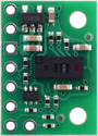
The datasheets for the LM74500-Q1 reverse voltage protection controller and LM74700-Q1 reverse voltage protection ideal diode controller provide additional information about adding a transient voltage suppressor (TVS) diode across the input as part of a more general input protection circuit. We have pads for an SMB-size TVS on the back side of the board for those interested in adding this kind of protection:
 |
As with our other electronics products, we make these at our Las Vegas, Nevada headquarters, so we can build custom versions with that TVS populated with a part of your choice (typical minimum quantities to make that worthwhile are around 200 pieces).
Are these interesting products? Would you want to see higher-current versions with bigger MOSFETs? Let us know in the comments or on our X and Facebook posts.
Introductory special discount! Try some out for as low as $1.16 each using our introductory special coupon, RVPINTRO (limit 5 per version)!
Related products
New products: D45V1ExFx tiny 65V max input step-down voltage regulators
 |
We just released the new D45V1ExFx line of small voltage regulators that can efficiently deliver up to 100 mA from input voltages up to 65 V. The small size, high efficiency, and wide input voltage range make these especially worth considering for low-power projects involving wildly fluctuating sources such as solar panels (you can see from my post yesterday that I have had solar on my mind lately) and other energy harvesting technologies. You might also just want the peace of mind of having the extra input voltage margin on something like a 24 V project that might have occasional spikes from something electrically noisy also being supplied by the same line. Or you might just have a few of these around for their small size and high efficiency at low currents.
 |
Typical efficiency of the Step-Down Voltage Regulator D45V1ExF5. |
|---|
(The 70-90% efficiency by itself is not particularly notable, but that efficiency is maintained to output currents of a few mA, which is kind of special.)
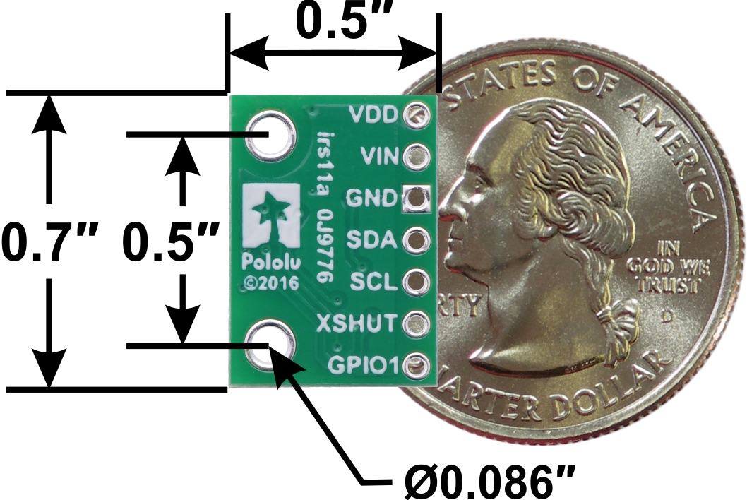
We are offering basically the same regulator circuit in two form factors. The D45V1E1Fx family has components on both sides of the PCB and measures just 0.3″ × 0.5″, making them our smallest step-down regulators.
 |
D45V1E1Fx step-down voltage regulator basic dimensions with US quarter for size reference. |
|---|
The larger D45V1E2Fx versions take up twice the area at 0.5″ × 0.6″, but they are thinner and, more importantly, offer two extra pins, including a precision enable input that can be used to set a cutoff voltage.
 |
D45V1E2Fx step-down voltage regulator pinout. |
|---|
We have a 1 MΩ pull-up resistor on the enable input, which means that if you pull that line low, you will lose about 1 μA per volt on your input. At higher input voltages, this current is higher than the quiescent (no-load) current the regulator consumes, so if you are just powering a microcontroller with a low idle or sleep current, you might be better off just using those low-power states to save energy, but if your load continuously draws more current, the shutdown feature could help prevent over-discharging your battery.
As with our other electronics products, we make these at our Las Vegas, Nevada headquarters, so we can quickly customize them for other output voltages besides our stock versions of 3.3 V, 5 V, and 12 V (depending on the customization, we can usually do custom production runs for setup fees starting around $250).
Introductory special discount! Try some out for only $3.33 each using our introductory special coupon, D45V1EXINTRO (limit 3 per version)!
Related products


New product: Dobot MG400 Desktop Cobot Robotic Arm
 |
We are pleased to announce that Pololu is now an authorized Dobot distributor, and our first offering from their catalog is a robot arm that we are especially excited about: the Dobot MG400 Desktop Cobot Robotic Arm. The Dobot MG400 is a departure from products typically available from Pololu. While the 8 kg (17 lb) unit is small for the collaborative robot world, it is much larger than typical Pololu products, and the cost is correspondingly higher as well. However, the price is still very competitive for what the robot arm offers, as the high ±0.05 mm positional repeatability, collision detection, and drag-to-teach ability make this cobot a compelling option for serious automation applications. With a footprint of 19 cm (7.5 in) square, the small size and low cost also make the Dobot MG400 accessible to many education and research applications that need more than a toy or hobby product. The following video shows off some of the arm’s features:
The Dobot MG400 has a maximum reach of 44 cm and can rotate through 320°, and it can lift payloads up to 500 g (18 oz). Dobot makes a sliding track module that substantially expands the operating envelope of this robot and a vision system, which are also available through Pololu (product pages for those are coming soon).
|
|


The picture below shows all of the accessories included with the MG400:
 |
Accessories included with the Dobot MG400 Desktop Cobot Robotic Arm. |
|---|
Please note that this arm does not include any grippers, but it does include a general-purpose flange for mounting end effectors that can be purchased separately from Dobot or other suppliers, or you can 3D print your own. A suction nozzle is included, but it requires an external air supply (compressor not included) to function.
The MG400 can be programmed a variety of ways, including through drag-to-teach positioning, a graphical programming interface, and Lua scripting. The controller in the base has plenty of I/O that makes it easy to integrate the robot into a bigger system.
 |
The pictures below show example MG400 applications with custom 3D-printed electromagnet end effectors used to manipulate Micro Metal Gearmotors for packaging and testing.
|
|


Related products

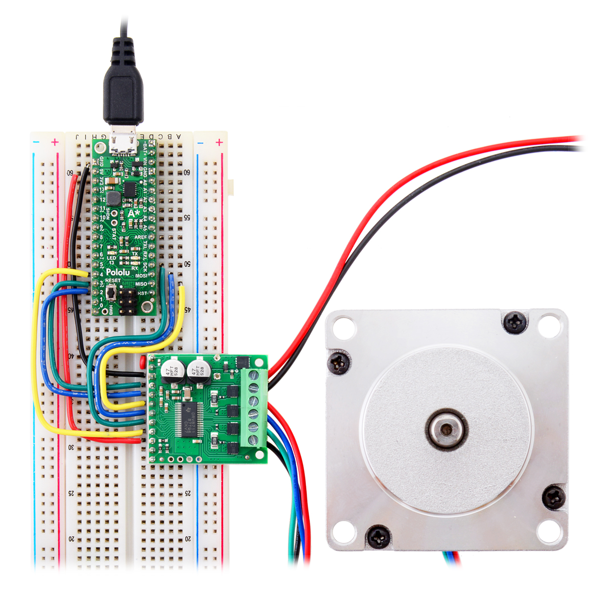
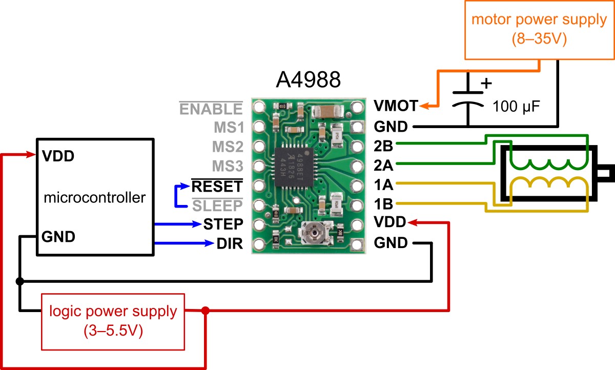
New products: A5984 Stepper Motor Driver Carriers
 |
We are excited to introduce our new series of stepper motor drivers based on the Allegro A5984 that offer an easy way to control bipolar stepper motors from supply voltages between 8 V and 40 V (absolute max). It’s hard to believe it’s been 15 years since we introduced the original A4983 stepper motor driver carrier in the small 16-pin form factor that would become ubiquitous for stepper motor drivers. We updated the product in 2011 when Allegro released the newer A4988, but since then we have released boards for stepper motor drivers from other semiconductor manufacturers, including Texas Instruments (most notably the DRV8825, and DRV8834, and more recently the DRV8434 series), Monolithic Power Systems (MP6500), STMicroelectronics (STSPIN820 and STSPIN220), and Toshiba (TB67S249FTG and TB67S279FTG). The new Allegro A5984 carriers, which can be used as drop-in replacements for the A4983/A4988 in many applications, bring us full circle with those original drivers, and with support from Allegro, we are able to offer them at extra low prices.
|
|

As with our other stepper driver products, we are offering the A5984 carriers with small trimmer potentiometers for setting the current limit. However, these can be a little fiddly to work with, so we are also offering several fixed-current versions for cases where you just want a particular set point without having to tune each board (for volume applications, we can do custom production runs with whatever set point you need). We also have two PCB options—a standard 2-layer version that is most economical for lower-current applications, and a 4-layer “Blue Edition” for maximum performance that can deliver up to 1.2 A continuous per phase (heat sinks and active air flow can bump that higher). The following table shows all the options:
 Adjustable Current, Blue Edition |
 Adjustable Current |
 Fixed 1.5A@5V / 1A@3.3V, Blue Edition |
 Fixed 1A@5V / 660mA@3.3V, Blue Edition |
 Fixed 750mA@5V / 500mA@3.3V |
 Fixed 500A@5V / 330mA@3.3V |
|
|---|---|---|---|---|---|---|
| Current limit (VDD = 5 V): |
adjustable (potentiometer) 1.2 A max continuous 2 A peak* |
adjustable (potentiometer) 1 A max continuous 2 A peak* |
1.5 A* | 1 A | 750 mA | 500 mA |
| Current limit (VDD = 3.3 V): |
1 A | 660 mA | 500 mA | 330 mA | ||
| Available versions: | ||||||
| PCB layers: | 4 | 2 | 4 | 4 | 2 | 2 |
| Price without header pins: | $5.95 | $5.75 | $5.75 | $5.75 | $5.49 | $5.49 |
| Price w/headers soldered: | $6.95 | $6.75 | $6.75 | $6.75 | $6.49 | $6.49 |
| * This current exceeds what the module can deliver continuously and is only achievable for short durations or with sufficient additional cooling (e.g. adding heat sinks or active air flow). | ||||||
Compared to those original A4988s, the A5984 carriers offer a number of improvements, including a higher maximum operating voltage, more microstep options and higher-resistance current sense resistors for improved microstepping performance, a fault output for reporting over-current faults, and an adaptive decay current control algorithm that automatically adjust the amount of fast decay to optimize the motor current waveform.
Introductory special discount! To celebrate the release of the A5984 carriers, the first hundred customers to use coupon code A5984INTRO can 15% off up to five units of each!
The following tables show our full selection of 16-pin stepper motor drivers:
 STSPIN220 |
 DRV8834 |
 A4988 (original) |
 A4988, Black Ed. |
 MP6500, Pot. CC |
 MP6500, Digital CC |
 A5984 |
 A5984, Blue Ed. |
|
|---|---|---|---|---|---|---|---|---|
| Driver chip: | STMicro STSPIN220 |
TI DRV8834 |
Allegro A4988 | MPS MP6500 | Allegro A5984 | |||
| Min operating voltage: | 1.8 V | 2.5 V | 8 V | 4.5 V | 8 V | |||
| Max operating voltage: | 10 V | 10.8 V | 35 V | 35 V | 40 V | |||
| Max continuous current per phase:(1) | 1.1 A | 1.5 A | 1 A | 1.2 A | 1.5 A | 1 A | 1.2 A | |
| Peak current per phase:(2) | 1.3 A | 2 A | 2 A | 2.5 A | 2 A | 2 A | ||
| Microstepping down to: | 1/256 | 1/32 | 1/16 | 1/8 | 1/32 | |||
| Board layer count: | 4 | 4 | 2 | 4 | 4 | 2 | 4 | |
| Special features: | low input voltage |
low input voltage |
digital current control |
versions also available with fixed current limits |
||||
| Available with headers soldered?: | Yes | Yes | Yes | Yes | Yes | Yes | Yes | Yes |
| 1-piece price: | $10.95 | $9.95 | $8.95 | $9.95 | $9.95 | $9.95 | $5.75 | $5.95 |
| 1 On Pololu carrier board, at room temperature, and without additional cooling. 2 Maximum theoretical current based on components on the board (additional cooling required). |
||||||||
 STSPIN820 |
 DRV8825 |
 TB67S279FTG |
 TB67S249FTG |
 DRV8434 |
 DRV8434A |
 DRV8434S, Pot. Max. |
 DRV8434S, 2A Max. |
|
|---|---|---|---|---|---|---|---|---|
| Driver chip: | STMicro STSPIN820 |
TI DRV8825 |
Toshiba TB67S279FTG |
Toshiba TB67S249FTG |
TI DRV8434 | TI DRV8434A | TI DRV8434S | |
| Min operating voltage: | 7 V | 8.2 V | 10 V | 10 V | 4.5 V | 4.5 V | 4.5 V | |
| Max operating voltage: | 45 V | 45 V | 47 V | 47 V | 48 V(3) | 48 V(3) | 48 V(3) | |
| Max continuous current per phase:(1) | 0.9 A | 1.5 A | 1.1 A | 1.6 A | 1.2 A | 1.2 A | 1.2 A | |
| Peak current per phase:(2) | 1.5 A | 2.2 A | 2 A | 4.5 A | 2 A | 2 A | 2 A | |
| Microstepping down to: | 1/256 | 1/32 | 1/32 | 1/32 | 1/256 | 1/256 | 1/256 | |
| Board layer count: | 4 | 4 | 4 | 4 | 4 | 4 | 4 | |
| Special features: | Auto Gain Control, ADMD |
Auto Gain Control, ADMD |
6 decay modes with 2 smart tune options |
Stall detect, smart tune ripple control decay |
SPI control, stall detect, 8 decay mode options |
|||
| Available with headers soldered?: | Yes | Yes | Yes | Yes | Yes | Yes | Yes | Yes |
| 1-piece price: | $18.95 | $15.95 | $11.75 | $13.95 | $10.95 | $13.95 | $13.95 | $13.95 |
| 1 On Pololu carrier board, at room temperature, and without additional cooling. 2 Maximum theoretical current based on components on the board (additional cooling required). 3 Not recommended for use with 48V batteries, which can be well above nominal when fully charged. |
||||||||
Related products


So many new Allegro current sensor carriers (58 and counting)!
 |
|
|||||
|
|
|
|||


 |
ACS71240 Current Sensor Carrier pinout. |
|---|
We have released a ton of new current sensors! These boards, based on Allegro current-sensing ICs, have analog outputs with voltage proportional to the AC or DC current passing through the sensor while offering full electrical isolation of the current path from the sensor’s electronics. This isolation allows them to be inserted anywhere in the current path, including on the high side, and because the current path resistance is on the order of 1 mΩ or less, there is minimal effect on the rest of the system.
As with all our other carrier boards, we designed these current sensors to be usable in real-world applications rather than just as evaluation boards. To that end, we have released compact carriers for use in space-constrained systems and larger modules with more connection options available for higher-current applications. The large carriers offer better thermal dissipation thanks to their 6-layer PCBs and increased surface area, and the holes and slots for the current path connection points accommodate thicker wires along with a variety of high-current connectors (e.g. lugs, solderless ring terminals, and 4-pin terminal blocks).
We also want these modules to be usable as evaluation boards, so we have standardized our compact and large form factors, making it easier to swap among different boards to compare different sensor ICs. Additionally, having different form factors available for the same sensor IC makes it possible to evaluate how things like PCB area and the number of copper layers affects the sensor’s thermal performance.
|
|
|


Here is a quick summary of the four new sensor families:
- ACS71240: low-cost measurement of bidirectional currents ranging from 10 A to 50 A, with dedicated versions for 3.3 V and 5 V systems. A unidirectional 50 A, 5 V version is also available.
- ACS37220: low-cost measurement of bidirectional currents ranging from 100 A to 200 A, with dedicated versions for 3.3 V and 5 V systems. These have extra-low 0.1 mΩ current paths through the sensor IC and user-configurable overcurrent fault thresholds.
- ACS72981: high-bandwidth (250 kHz) measurement of unidirectional or bidirectional currents from 50 A to 200 A, with dedicated versions available for 3.3 V and 5 V systems.
- CT432/CT433: extra high-bandwidth (1 MHz), low response time (300 ns) measurement of unidirectional or bidirectional currents from 20 A to 70 A, with dedicated versions available for 3.3 V and 5 V systems. Unlike the other Allegro sensor families we carry, which use Hall effect sensing, the CT432/CT433 sensors use tunneling magnetoresistance (which Allegro calls XtremeSense™ TMR) and are optimized for high dV/dt applications.
Here’s our full list of active and preferred current sensors:
 |
 |
 |
 |
 |
 |
 |
 |
 |
|
|---|---|---|---|---|---|---|---|---|---|
| ACS711 Current Sensor Carriers |
ACS71240 Current Sensor Carriers |
ACS724 Current Sensor Carriers |
ACS37220 Current Sensor Compact Carriers |
ACS37220 Current Sensor Large Carriers |
ACS72981 Current Sensor Compact Carriers |
ACS72981 Current Sensor Large Carriers |
CT432/CT433 TMR Current Sensor Compact Carriers |
CT432/CT433 TMR Current Sensor Large Carriers |
|
| Sensor IC | Allegro ACS711KEXT |
Allegro ACS71240 |
Allegro ACS724LLCTR |
Allegro ACS37220 | Allegro ACS72981xLR | Allegro CT432/CT433 | |||
| Sensing technology | Hall effect | Hall effect | Hall effect | Hall effect | Hall effect | XtremeSense™ TMR (tunneling magnetoresistance) |
|||
| Logic voltage range (V) | 3.0–5.5 | 3.3V versions: 3.0–3.6 5V versions: 4.5–5.5 |
4.5–5.5 | 3.3V versions: 3.15–3.45 5V versions: 4.5–5.5 |
3.3V versions: 3.0–3.6 5V versions: 4.5–5.5 |
3.3V versions: 3.0–3.6 5V versions: 4.75–5.5 |
|||
| Current range / sensitivity | Bidirectional:(1) ±15.5 A / 90 mV/A ±31 A / 45 mV/A |
3.3V Bidirectional: ±10 A / 132 mV/A ±30 A / 44 mV/A ±50 A / 26.4 mV/A 5V Bidirectional: ±10 A / 200 mV/A ±30 A / 66 mV/A ±50 A / 40 mV/A 5V Unidirectional: 0–50 A / 80 mv/A |
5V Bidirectional:(2) ±2.5 A / 800 mV/A ±5 A / 400 mV/A ±10 A / 200 mV/A ±20 A / 100 mV/A ±30 A / 66 mV/A ±50 A / 40 mV/A 5V Unidirectional:(2) 0–5 A / 800 mv/A 0–10 A / 400 mv/A 0–20 A / 200 mv/A 0–30 A / 133 mV/A |
3.3V Bidirectional: ±100 A / 13.2 mV/A ±150 A / 8.8 mV/A 5V Bidirectional: ±100 A / 20 mV/A ±150 A / 13.3 mV/A ±200 A / 10 mV/A |
3.3V Bidirectional: ±100 A / 13.2 mV/A ±150 A / 8.8 mV/A 5V Bidirectional: ±100 A / 20 mV/A ±150 A / 13.3 mV/A ±200 A / 10 mV/A |
3.3V Bidirectional:(1) ±50 A / 26.4 mV/A ±100 A / 13.2 mV/A ±150 A / 8.8 mV/A 3.3V Unidirectional:(1) 0–50 A / 52.8 mv/A 0–100 A / 26.4 mv/A 0–150 A / 17.6 mv/A 0–200 A / 13.2 mv/A 5V Bidirectional:(2) ±50 A / 40 mV/A ±100 A / 20 mV/A ±150 A / 13.3 mV/A ±200 A / 10 mV/A 5V Unidirectional:(2) 0–100 A / 40 mv/A 0–150 A / 26.7 mv/A |
3.3V Bidirectional:(1) ±50 A / 26.4 mV/A ±100 A / 13.2 mV/A ±150 A / 8.8 mV/A 3.3V Unidirectional:(1) 0–50 A / 52.8 mv/A 0–100 A / 26.4 mv/A 0–150 A / 17.6 mv/A 0–200 A / 13.2 mv/A 5V Bidirectional:(2) ±50 A / 40 mV/A ±100 A / 20 mV/A ±150 A / 13.3 mV/A ±200 A / 10 mV/A 5V Unidirectional:(2) 0–100 A / 40 mv/A 0–150 A / 26.7 mv/A |
3.3V Bidirectional: ±20 A / 50 mV/A ±30 A / 33.3 mV/A ±50 A / 20 mV/A 3.3V Unidirectional: 0–50 A / 40 mv/A 0–65 A / 30.8 mv/A 5V Bidirectional: ±20 A / 100 mV/A ±30 A / 66.7 mV/A ±50 A / 40 mV/A ±65 A / 30.8 mV/A 5V Unidirectional: 0–50 A / 80 mv/A 0–70 A / 57.1 mv/A |
3.3V Bidirectional: ±50 A / 20 mV/A 3.3V Unidirectional: 0–50 A / 40 mv/A 0–65 A / 30.8 mv/A 5V Bidirectional: ±50 A / 40 mV/A ±65 A / 30.8 mV/A 5V Unidirectional: 0–50 A / 80 mv/A 0–70 A / 57.1 mv/A |
| IC path resistance | 0.6 mΩ | 0.6 mΩ | 0.6 mΩ | 0.1 mΩ | 0.2 mΩ | 1 mΩ | |||
| PCB | 2 layers, 2-oz copper |
2 layers, 2-oz copper |
2 layers, 2- or 4-oz copper(4) |
2 layers, 2-oz copper |
6 layers, 2-oz copper |
6 layers, 2-oz copper |
6 layers, 2-oz copper |
2 or 4 layers(5), 2-oz copper |
6 layers, 2-oz copper |
| Max bandwidth | 100 kHz | 120 kHz | 120 kHz(3) | 150 kHz | 250 kHz | 1 MHz | |||
| Size | 0.7″ × 0.8″ | 0.7″ × 0.8″ | 0.7″ × 0.8″ | 0.7″ × 0.8″ | 1.4″ × 1.2″ | 0.7″ × 0.8″ | 1.4″ × 1.2″ | 0.8″ × 1.1″ | 1.4″ × 1.2″ |
| Overcurrent fault output | User-configurable threshold | ||||||||
| Common-mode field rejection | |||||||||
| Non-ratiometric output | |||||||||
| 1-piece price | $4.85 | $5.25 | $9.95 – $11.49 | $6.95 | $10.95 | $13.95 | $16.95 | $12.95 | $16.95 |
(1) Sensitivity when Vcc = 3.3 V; sensitivity is ratiometric.
(2) Sensitivity when Vcc = 5 V; sensitivity is ratiometric.
(3) Bandwidth can be reduced by adding a filter capacitor.
(4) ±50A version uses 4-oz copper PCB; all other versions use 2-oz copper.
(5) 50A and higher versions use 4-layer PCB; all other versions use 2-layer PCB.
More sensors are coming, and we will be releasing them as they become available. Do you have a favorite current sensor? Let us know in the comments!
New product: Pololu H2 High-Power Motor Driver 36v11 CS
 |
We’re excited to introduce our new 60V-max H2 High-Power Motor Driver 36v11 CS, which joins our lineup of high-power motor drivers as the new highest-voltage option. Like our other high-power motor drivers, this board is a discrete MOSFET H-bridge that is designed to drive large brushed DC motors. The H2 36v11 can supply a motor with continuous currents up to 11 A over a wide 5 V to 60 V (absolute maximum) operating range. The board also features reverse-voltage protection and an on-board bidirectional current sensor that provides a direct measurement of the motor current.
|
|


The H2 driver is designed to be a near drop-in replacement for its predecessor and for our lower-voltage G2 drivers, with an identical form factor and a similar pinout. Compared to its predecessor, the H2 version adds improvements such as reverse-voltage protection, current sensing, and compatibility with 3.3V systems (as well as 5V). Compared to the newer G2 drivers, the main differentiator is the wider operating voltage range, but the H2 36v11 CS also adds an on-board bidrectional current sensor that provides a direct measurement of the motor current, even when the driver isn’t actively driving. There are also differences in the pinout, control interface, and some aspects of the operation, so please see the H2 product page for more information on compatibility between it, its prececessor, and the G2 versions.
Introductory special discount! To celebrate the release of the H2 36v11 CS, the first hundred customers to use coupon code H236V11CSINTRO can get up to three units for just $34.95 each!
New product: VL53L4CD Time-of-Flight Distance Sensor Carrier
 |
 |
We are pleased to announce the release of our new low-cost time-of-flight distance sensor featuring ST’s VL53L4CD. The VL53L4CD has a detection range of 1 mm to 120 cm (4 ft) with a resolution of 1 mm and an update rate of up to 100 Hz. This distance sensor is notable for being able to accurately measure the distances to objects even as they are almost touching the sensor face.
One interesting feature of the VL53L4CD is its Ultra-Low Power mode, which allows it to act as a basic proximity detector with greatly reduced average current consumption (less than 100 μA in some cases). In this mode, the sensor does not output distance and other data as usual; it simply raises an interrupt when a target is detected. This functionality is enabled with ST’s VL53L4CD ULP API (application programming interface), and the ULP and standard drivers can be used together to let the VL53L4CD switch from low-power proximity detection to accurate ranging once it sees a target. (ULP drivers are now available from ST for the VL53L1X and VL53L3CX as well.)
Introductory special discount! With the release of the VL53L4CD carrier, we are also bringing back introductory special discounts, which was how we celebrated the release of new products prior to the pandemic and ensuing parts shortages. The first hundred customers to use coupon code VL53L4CDINTRO can get up to five units for just $8.88 each!
The VL53L4CD is the new lowest-cost member of the ST FlightSense ToF sensor family, which includes higher-performance alternatives with longer ranges and capable of multi-target detection:
 VL6180X carrier |
 VL53L4CD carrier |
 VL53L0X carrier |
 VL53L1X carrier |
 VL53L3CX carrier |
 VL53L5CX carrier |
 VL53L7CX carrier |
 VL53L8CX carrier |
|
|---|---|---|---|---|---|---|---|---|
| Maximum range:(1) | 60 cm | 120 cm | 200 cm | 400 cm | 500 cm | 400 cm | 350 cm | 400 cm |
| Minimum range: | ~10 mm | 1 mm | ~30 mm | 40 mm | 10 mm | 20 mm | ||
| Field of view: | 25° | 18° | 25° | 15° to 27° diagonal, programmable |
25° | 65° diagonal, up to 8×8 zones |
90° diagonal, up to 8×8 zones |
65° diagonal, up to 8×8 zones |
| Other features: | ambient light sensing, low memory footprint(2) |
low memory footprint(2), ultra-low power mode |
low memory footprint(2) | low memory footprint(2), ultra-low power mode |
multi-target detection, ultra-low power mode |
multi-target detection | multi-target detection | multi-target detection, improved performance in ambient light |
| Maximum update rate:(1) | ~150 Hz | 100 Hz | 50 Hz | 100 Hz | 125 Hz | 60 Hz | ||
| Operating voltage range: | 2.6 V to 5.5 V | 2.5 V to 5.5 V | 3.2 V to 5.5 V | |||||
| Regulator voltage: | 2.8 V | 3.3 V | 1.8 V and 3.3 V | |||||
| Typical active-ranging supply current: |
25 mA | 25 mA | 20 mA | 20 mA | 20 mA | 100 mA | ||
| Peak supply current: | 40 mA | 150 mA | ||||||
| Interface: | I²C | I²C, SPI | ||||||
| Dimensions: | 0.5″ × 0.7″ | 0.5″ × 0.9″ | ||||||
| 1-piece price: | $19.95 | $13.95 | $19.95 | $22.95 | $19.95 | $19.95 | $19.95 | $24.95 |
| 1 Effective range and update rate depend on configuration, target, and environment. 2 Suitable for use with typical 8-bit MCUs. |
||||||||


Home | Forum | Blog | Support | Ordering Information | Lists | Distributors | BIG Order Form | About | Contact
© 2001–2026 Pololu Corporation


