Pololu Blog » Engage Your Brain »
New products: Jrk G2 USB Motor Controllers with Feedback
After many months or years of work (depending on how you look at it), I am happy to introduce our newest motor controllers, the Jrk G2 USB Motor Controllers with Feedback, which we are releasing today in four power variants:
 Jrk G2 18v19 |
 Jrk G2 24v13 |
 Jrk G2 18v27 |
 Jrk G2 24v21 |
|
|---|---|---|---|---|
| Recommended max operating voltage: |
24 V(1) | 34 V(2) | 24 V(1) | 34 V(2) |
| Max nominal battery voltage: |
18 V | 28 V | 18 V | 28 V |
| Max continuous current (no additional cooling): |
19 A | 13 A | 27 A | 21 A |
| Dimensions: | 1.4″ × 1.2″ | 1.7″ × 1.2″ | ||
1 30 V absolute max.
2 40 V absolute max.
 |
The main purpose of the Jrk G2 family is to enable feedback-based control of DC brushed motors, simplifying closed-loop control of things like the position of an actuator. An example that is probably familiar to most of us is the common hobby servo that has an output shaft that can rotate to various positions as commanded over a simple interface. The Jrk motor controllers can be used for giant versions of those servos, and they can also be used in many other systems as long as you can somehow get feedback in the form of an analog voltage or a frequency. Analog voltage feedback is often easy to get from potentiometers that can serve as angle or position sensors.
The frequency feedback feature is handy for maintaining a speed of a motor independent of your supply voltage and motor load. You might use that kind of feature to run a treadmill at some set speed independent of the weight of the lab rats on it or to stir some jar of goop at a constant rate as the goop gradually thickens. With mobile robot applications, it can be handy to have a motor controller that will make your wheel go at the speed you set independent of whether the robot is on a hard floor or a carpet. (The Jrks do not support quadrature encoders, but you can use one channel of a quadrature encoder as the tachometer for the Jrk. In some applications, keeping track of absolute position is not necessary, or the quadrature encoder can be monitored directly by a main controller that could still benefit from the closed-loop speed control being taken care of by the motor controller.)
To control a wide range of motors in a variety of applications, it’s important to be able to configure a lot of parameters, which makes the Jrk’s USB connection and free configuration utility software extremely important. Even if you ultimately want to use your Jrk in a radio control installation or command it over I²C from your favorite embedded controller, it’s very convenient to be able to set everything up from your computer.
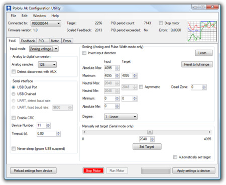 |
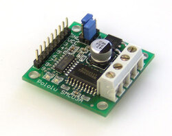
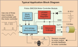
That screenshot is actually of the utility for the original Jrks, which we released almost 9 years ago (I announced those on the forum because we did not have this blog back then). You might notice on some older web pages that we referred to the original Jrks as our second-generation feedback controllers. The really original ancestor to today’s new motor controllers is this product we called simply Pololu 3A Motor Controller with Feedback, which we released at the beginning of 2005. Here are a picture and block diagram of that controller:
|
|
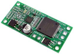 |
Candice and I were probably still running Pololu out of our house back when we started work on that controller, and it’s probably the last product of ours for which Candice wrote some of the firmware. That controller led to the development of a larger, customized controller (similar to our SMC04 High-Power Motor Controller with Feedback) and an even higher-power version that was used on control cables of large autonomous parachutes for the military.
Back to the new Jrk G2 family: these new controllers are in many ways a refinement of the original Jrks, which have been used all over the world in applications from animatronic displays to motion simulators and even full-sized airplanes. The most noticeable improvement on the four Jrk G2 controllers we are releasing today is the increased power available from their discrete MOSFET H-bridges. The G2 high-power motor driver design is part of the reason for the “G2” in the new Jrk family name, though we plan on releasing lower-power, smaller Jrk G2 products later this year. The new driver technology, along with going to double-sided PCB assembly and four-layer PCBs, allowed us to make much higher-power controllers that are smaller than the old Jrk 12v12, which used to be our highest-power version.
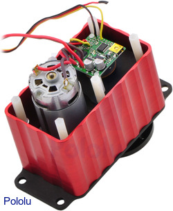
The Jrk G2 24v13 and 24v21 in particular open up new application opportunities because they can operate off of 24 V power rails, making them appropriate for huge linear actuators (note that we only carry 12 V versions right now, partly because we did not have controllers that we could recommend for 24 V use). It’s exciting that these tiny boards can control such huge actuators, and the size difference is so big it’s difficult to convey in a picture:
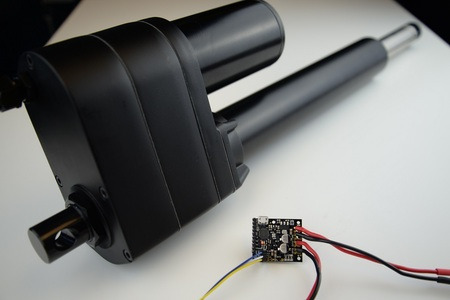 |
The size difference makes it difficult to get a Jrk G2 24v13 and an industrial-duty linear actuator in the same picture. |
|---|
Other features new to the G2 Jrks are an I²C interface option and an improved tachometer/frequency feedback mode that now offers pulse width measuring rather than only frequency counting to allow for better control of low-speed motors with lower-resolution encoders or tachometers. Here is a summary of the main features of the Jrk G2 motor controllers:
- Easy open-loop or closed-loop control of one brushed DC motor
- A variety of control interfaces:
- USB for direct connection to a computer
- TTL serial operating at 5 V for use with a microcontroller
- I²C for use with a microcontroller
- RC hobby servo pulses for use in an RC system
- Analog voltage for use with a potentiometer or analog joystick
- Feedback options:
- Analog voltage (0 V to 5 V), for making a closed-loop servo system
- Frequency pulse counting (for higher-frequency feedback) or pulse timing (for lower-frequency feedback), for closed-loop speed control
- None, for open-loop speed control
- Note: the Jrk does not support using quadrature encoders for position control
- Ultrasonic 20 kHz PWM for quieter operation (can be configured to use 5 kHz instead)
- Simple configuration and calibration over USB with free configuration software utility
- Configurable parameters include:
- PID period and PID constants (feedback tuning parameters)
- Maximum current
- Maximum duty cycle
- Maximum acceleration and deceleration
- Error response
- Input calibration (learning) for analog and RC control
- Optional CRC error detection eliminates communication errors caused by noise or software faults
- Reversed-power protection
- Field-upgradeable firmware
- Optional feedback potentiometer disconnect detection
As with all of our new product releases this year, we are offering an extra introductory discount: the first 100 customers to use coupon code JRKG2INTRO can get 40% off up to three units. (Click to add the coupon code to your cart.)

