Pololu Blog »
David and Fang's dead reckoning robot based on the mbed LPC1768
 |
Several people here at Pololu made robots to compete in the LVBots Dead Reckoning Competition last week. This post is about the robot I made along with another engineer here.
Dead reckoning is the process of continuously calculating your position using internal sensors that tell you something about what speed and direction you are going. In our dead reckoning competitions, robots demonstrate that they are capable of dead reckoning by following a long, twisting line drawn on the floor and then driving back to their starting point. The line functions as a user interface that directs the robots through a sequence of moves for which it was not preprogrammed. The robots are scored based on the time they took and how close they were to the starting point at the end. For more information, see the LVBots dead reckoning rules (23k pdf).
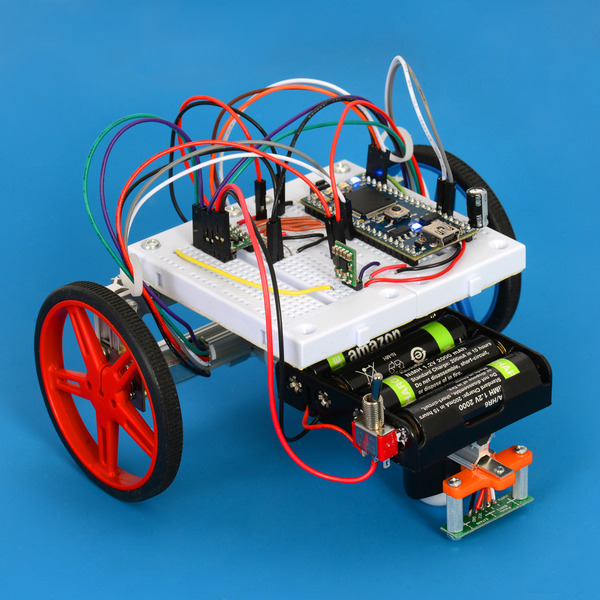
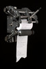
The main components we used for our robot are labeled in the picture below:
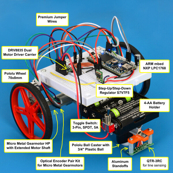 |
Electronics
The sensor we used for dead reckoning was a Pololu optical encoder pair kit attached to two 30:1 Micro Metal Gearmotors HP with Extended Motor Shaft. The encoders allow the robot to sense how far and in which direction the motor shaft is rotating.
The encoders were connected directly to I/O lines on the main processor of our robot, which was an ARM mbed NXP LPC1768 Development Board. We chose this mbed because it has a powerful 32-bit ARM Cortex-M3 processor, so doing the dead reckoning calculations would not be much of a burden on the CPU.
Since the outputs of the optical encoder pair kit are direct phototransistor outputs without any signal conditioning, it really helps to have an oscilloscope when setting up the encoders. When I soldered the first encoder and installed the included 5-tooth wheel, I saw that the signal from the encoder was getting pulled low pretty strongly during the low phase, but was not going high enough during the high phase. I was able to fix this by enabling pull-up resistors on the mbed’s I/O lines. However, when I soldered the second encoder, that same solution did not work, probably due to differences in the sensors. I switched from the 5-tooth wheel to the 3-tooth wheel, which made the contrast better. I disabled the pull-up resistors after making that change, and the signals from the encoders were still good enough to be read properly by the mbed.
The robot was powered by four rechargeable AA batteries in a battery holder. We soldered a toggle switch in line with the battery pack’s red wire to allow us to turn the robot on and off, and glued the switch to the battery pack. The switch was oriented so that the on position of the switch pointed away from the body of the robot, making it slightly easier to turn off the robot if it ever got out of control.
The battery power was connected directly to a DRV8835 Dual Motor Driver Carrier. I am not sure how good the breadboard is for carrying motor current, so I placed all the wires carrying high current for the motors directly adjacent to the motor driver. The motor driver was set to phase-enable mode and controlled by two PWM outputs and two digital outputs from the mbed. The mbed’s I/O lines are pulled up by default, and in some cases this caused the motors to run when we didn’t want them to. To solve this, we added a 1 kΩ resistor between each enable line and GND. The pull-down resistors were significantly stronger than the mbed’s internal pull-up resistors and guaranteed that the motor would not turn on unless the mbed actually drove those lines high.
Initially, I powered the mbed directly from the batteries. The mbed’s VIN pin can take a voltage between 4.5 V and 9.0 V, and four NiMH batteries have a nominal voltage of 4.8 V, so it mostly worked. However, when I was testing the motors, I noticed that trying to quickly turn on the motors would sometimes make the mbed reset. This is because the motors would draw a sudden burst of current, causing the battery voltage to drop below the mbed’s allowed range. To solve this, I added a Pololu 5V Step-Up/Step-Down Voltage Regulator S7V7F5 to produce a stable 5 V output for powering the mbed. I mounted the regulator on the included right angle male headers so that it would take up less space on the breadboard by standing up straight. Even in that orientation, this tiny regulator is still shorter than a lot of the other things plugged into the breadboard. For extra protection, I added a 100 μF electrolytic capacitor, similar to Pololu item #882, between the mbed’s GND and VIN pins and I put it as close as possible to the mbed.
The S7V7F5 regulator was not powered directly from the batteries; we powered it from the VMM pin on the DRV8835. This helped protect the rest of the system from the effects of accidentally plugging in power backwards.
To sense the line, we used a QTR-3RC Reflectance Sensor Array. We initially used the QTR-3A and it seemed to work, but I was unable to actually follow a line because of spurious noise spikes on the three analog inputs from the mbed that were connected to the QTR-3A. The spikes were only visible in the digital data from the analog inputs; I could not see them using an oscilloscope on those lines. The spikes seemed to have too high of an amplitude and lasted for too long to be easily filtered out in software, so I switched to the QTR-3RC, which worked much better.
For a user interface, we used the four user-controllable LEDs on the mbed and also put a mini pushbutton switch on the breadboard.
For wiring between different points on the breadboard, I used wires from our jumper wire kits. These wires have a solid core so they can be connected directly to a breadboard. To connect the breadboard to other parts of the robot, I used premium jumper wires.
Mechanical structure
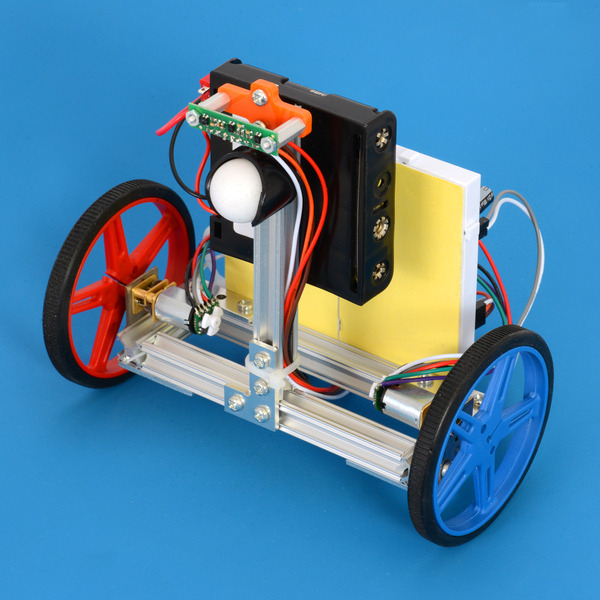 |
The main structure of the robot was made with MicroRAX pieces. Everything was screwed together, allowing us to easily unscrew it to make modifications. The mbed and most of the electronics were installed on two linked 270-point breadboards. We used laser cutters to make metal plates for attaching the motors, and also to make an orange plastic piece for mounting the line sensor. The line sensor was attached to the orange piece and positioned at the right height using two 1/2" aluminum standoffs.
We used two 70×8mm diameter Pololu wheels. The robot’s third point of contact with the ground was provided by a Pololu Ball Caster with 3/4" Plastic Ball.
Data logging
One nice thing about the mbed NXP LPC1768 is that it has 32 KB of RAM. I set aside 8 KB of RAM for a log and stored the coordinates of the robot every 50 ms during some of the test runs. I made it so the robot can send that data to a PC over USB after the test run is done. I used the log feature of Tera Term to save that log to a file and then I wrote a Ruby script to convert that to an SVG file. I used Inkscape to overlay the data points onto an actual photograph of the test course, as shown below.
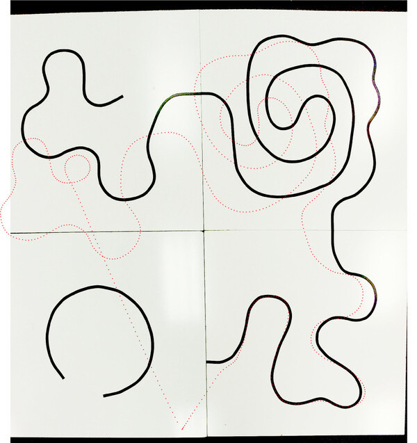 |
Results
During test runs, the robot was typically able to follow a long path and then drive back to within 18 inches of the starting point. However, during the actual competition, which had a more challenging course, our best distance was 47 inches. This earned us third place.
Source code
The entire source code for the program we wrote for the mbed is available online.
What I would do differently next time
The next time I do a dead reckoning contest, I plan to replace this robot’s motors with different micro metal gearmotors that have a higher gear ratio. The 30:1 HP motors we used were fast and hard to control. At certain points during development, the robot would just stop moving because the motors did not have enough torque, and a light push would get it going again. To fix this, I just increased the maximum duty cycle of the motors. I could have also used the encoders in my code to detect when the robot is not moving and apply more power to the motors, but it would be simpler to just use motors with more torque next time. In the final code, I never drove them at a duty cycle above 33% but the robot was still fast enough.
Related products


-
ToDo and Babel by Chris Eckert
- 17 March 2014Chris Eckert makes devices that explore the artistic potential of factory automation. One of his works, entitled ToDo, is an automated wall...
3 comments

You can find out more about the code and how to use it here: http://wp.me/p493sy-jy
The Navigator is explained here: http://wp.me/p493sy-fA
And the Pilot is explained here: http://wp.me/p493sy-gs

Post a comment


Home | Forum | Blog | Support | Ordering Information | Lists | Distributors | BIG Order Form | About | Contact
© 2001–2026 Pololu Corporation
