Pololu Blog » Engage Your Brain »
Gettin' all up in your servos
 |
Having introduced servos and their role in a typical hobby radio control application, I will now focus on the servo itself: its parts, what is inside, and a bit of how it works. We will look at a few different servos along the way to better understand what servos have in common and how they differ.
Servos from the outside
From the outside, the servo has a few basic parts:
- Case
- Mounting tabs
- Output shaft
- Servo horn
- Cable
- Connector
These parts are labeled below on micro-, standard-, and giant-sized servos:
|
|
|

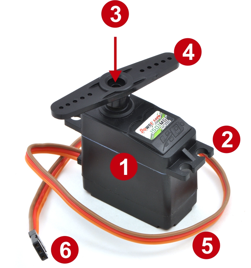
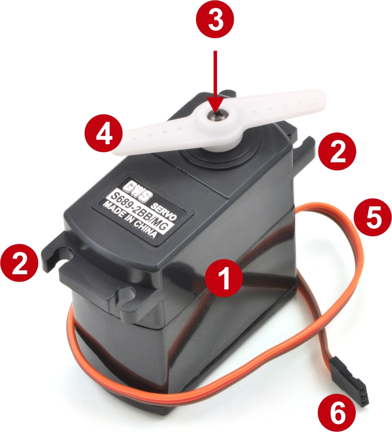
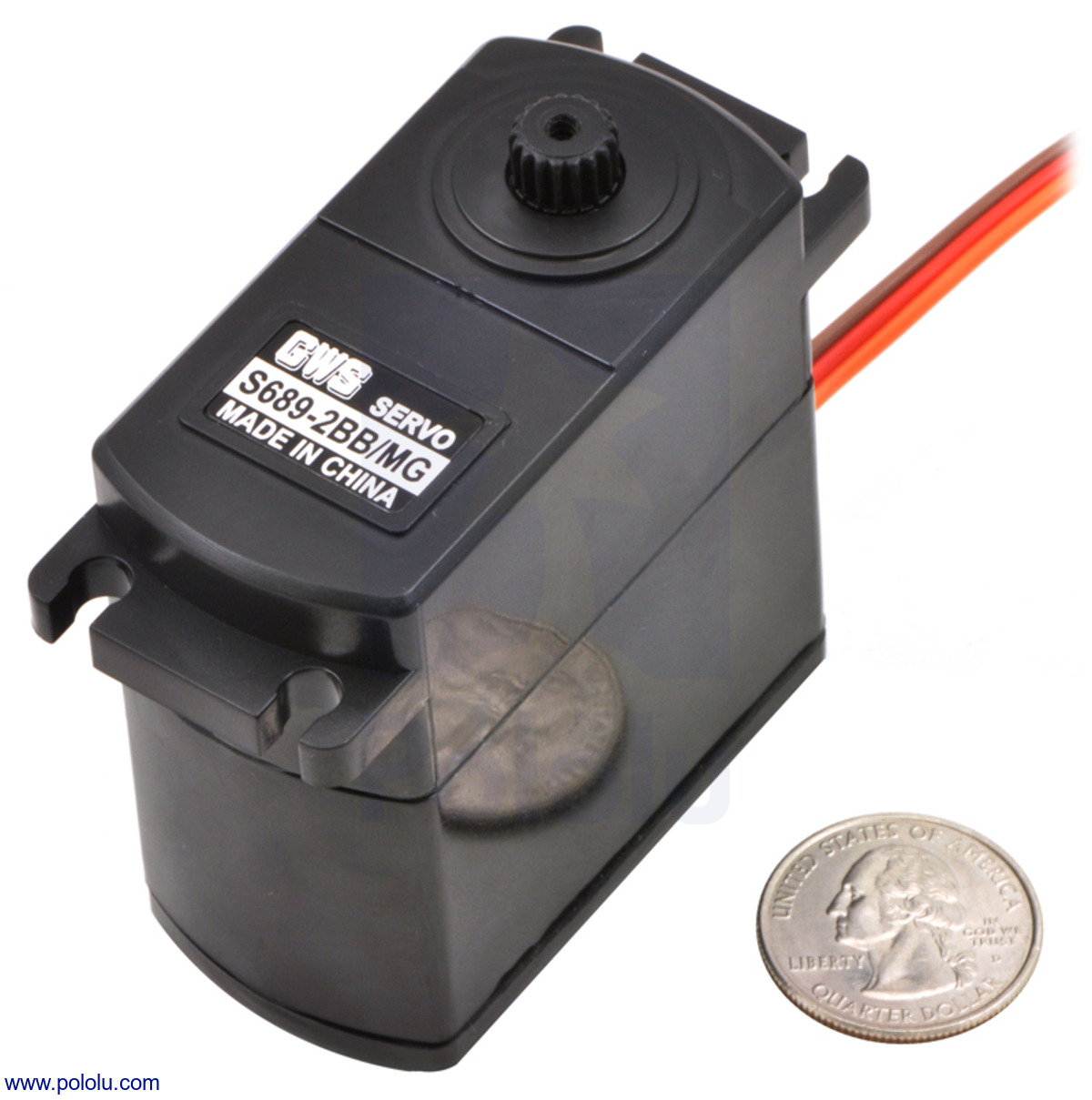
You can look at the connectors, which are the same size on all three, to get a sense for the servos’ relative sizes. Let us consider each of the parts in a bit more detail.
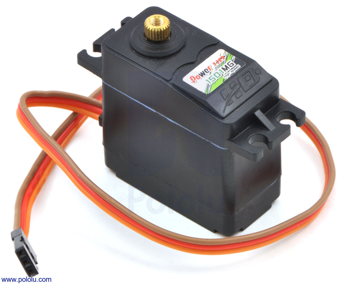
1. Case
 |
The case holds together most of the servo and protects its internal components. The case is usually made of three plastic sections screwed together, but some really small servos might only be held together by heat shrink or stickers. In some fancy servos, the middle section of the case is made of metal for better heat dissipation to keep high-performance motors and electronics from overheating. Some servos are better sealed than others for moisture protection with extra gaskets or O-rings between the case segments and on the screws. In the picture to the right, the top of the case is removed, showing the blue O-ring between the top segment and middle segment.
2. Mounting tabs
The mounting tabs are molded into the case, but I am listing them separately because of their distinct function. In a typical installation into a sheet of material, a rectangular hole that is big enough for the case but smaller than the tabs is cut out; the tabs can then be screwed down to the sheet. Many servos are supplied with a small bag of hardware including screws and grommets for mounting the servo with some shock or vibration protection. Since the mounting tabs do not involve the workings of the servo, they can be cut off for space-constrained installations. Servos, especially small ones, are often mounted with double-sided tape or cable ties.
3. Output shaft
The output shaft is usually not visible until we take off the servo horn; here are the same servos as before with the horns removed:
|
|
|

The output shafts have splines, little grooves along the shaft, and screw holes for securely mounting servo horns without any slipping. Servo output shafts are generally not standardized: different servo sizes require different outputs, and even within standard-size servos, different manufacturers use different splines that are incompatible with each other. If you ever need to count the splines, a digital camera can function as a good magnifying glass or microscope: it’s much easier to take a picture, zoom in on your screen, and count the splines than to try to count them directly on the servo.
4. Servo horns
Servo horns are attachments that fit over the output shaft that allow you to mechanically link the servo output to the rest of your mechanism. Servos are usually supplied with an assortment of servo horns:
 |
Typical assortment of horns and mounting hardware supplied with servos. |
|---|
Unfortunately, the exact horns included are usually not specified and can vary. And, since servo output shafts and their splines vary, horns are often incompatible between brands and models of servo. Various specialty horns, for instance extra large ones and metal ones, are available from some servo manufacturers or as aftermarket accessories. Another type of specialty horn is the “servo saver”, which has an integrated spring to limit shocks transmitted from the external mechanism to the servo.
5. Cable
Servos have three-wire cables that supply power and commands to servos. The cables are typically six to twelve inches long, with 22 gauge and thinner wires (smaller servos tend to have shorter and thinner wires). Since the connectors have become more standardized, the order of the wires has also become standardized, with the power wire in the middle flanked by ground and signal wires. However, the color schemes still vary. Common ones are:
- Black for ground, red for power, white for signal
- Brown for ground, red for power, and orange for signal
- Black for ground, red for power, blue for signal
My preference is for the first scheme since that offers the most contrast; the orange and brown of the second scheme can look kind of similar with bad lighting, as can the blue and black of the third approach. You are almost guaranteed to instantly destroy a servo if you connect power backwards, so make sure you double-check your connections.
6. Connector
The three-conductor cable is terminated with a 3-pin connector, which is almost universally a female connector with 0.1" spacing. Unfortunately, much of the RC world calls this female connector a male connector. As with the cable colors, the connector colors can vary. The “Futaba” plug, on the left in the picture below, has an extra polarizing tab (on the left side in the picture) that can be cut off to match the others, which are called “JR” (center) and “Airtronics Z” (right). Some of the brand names might vary by country; the most common names I see from generic servo makers in China are “Futaba” and “JR”.
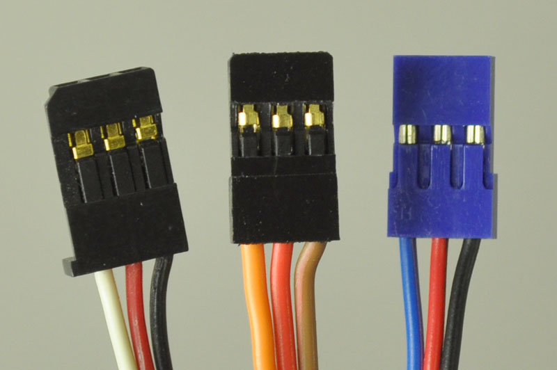 |
Common RC servo connectors. From left to right: Futaba, JR, Airtronics Z. |
|---|
Viewed from the end, the connectors have two beveled corners to help prevent plugging servos in backwards. That prevention mechanism relies on the RC receiver having a corresponding cutout, which is not present on most servo controllers and other electronics a robot builder might be using instead of the usual radio control components. Again: pay attention when plugging in your servos!
Servos from the inside
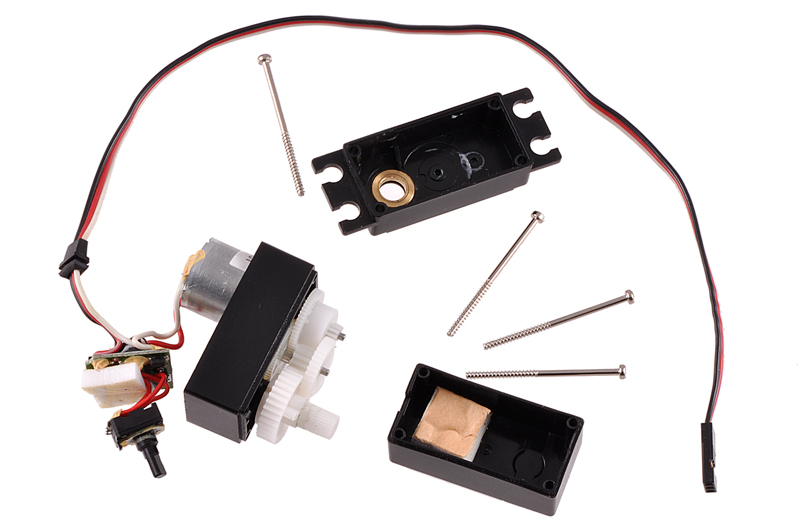
If we take apart a servo, we can see its key sub-systems:
- Motor
- Gearbox
- Position sensor
- Motor control electronics
This picture shows those parts on a standard-size servo. Many servos have the motor and sensor soldered to a single circuit board, which can make disassembly a bit more difficult.
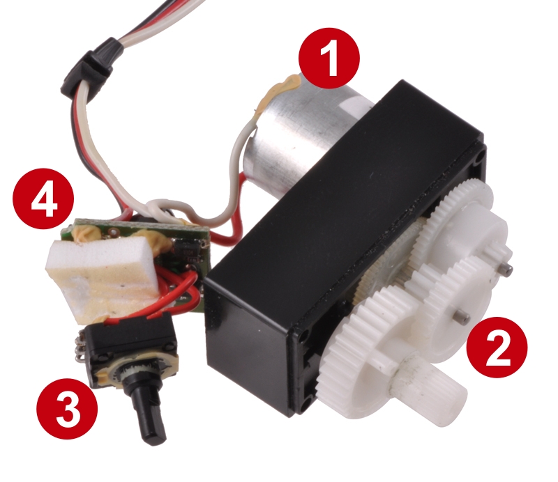 |
Identification of the major components of a disassembled servo. |
|---|
1. Motor
Since servos are electric actuators, it should be no surprise that there is a motor inside. The motor sets the ultimate power the servo can output, assuming the electronics or gearbox doesn’t limit it. Given that servos are often designed for weight-sensitive applications and that the motor is usually the heaviest part of the servo, we can expect servo manufacturers to pick the optimum motor to match the rest of the servo, and in general, there’s not much point to concerning ourselves with the motor separately from the rest of the servo. (From an abstractions perspective, the only electrical access we have to the motor is through its control electronics, and the only mechanical access is through its gearbox; there is therefore little to be gained from considering the motor in isolation.) The one place where motor details show up in servo marketing is if the servo has a coreless motor, which has a lighter rotor and can accelerate faster.
2. Gearbox
Small motors tend to be useless without a gearbox to convert their high speed and low torque into a more practical combination of speed and torque. The gear ratio is rarely specified since end users are concerned with the combined performance of the motor and gearbox, but given that the motors easily run upwards of ten thousand RPM and the output shaft turns at the equivalent of around 60 RPM (60 degrees, or 1/6 of a rotation, in 0.15 seconds, or about 1/6 of a second), we know the gear ratio is over 100:1. When manufacturers offer multiple speed versions of effectively the same servo and at the same price, the only difference between the servos is usually the gear ratio.
The output shaft and the final gear are usually one part, and in better-quality servos, that final gear is supported by ball bearings. On some servos, particularly giant ones, there might be ball bearings on more than just the final shaft.
The gears can be made of various plastics or metals. Cheaper servos tend to have plastic gears, though some high-end servos also use plastic gears (possibly with fancy names like Karbonite). Metal gears are supposed to be stronger than plastic gears, but they can be heavier, which can add to the overall weight of the servo and also limit the acceleration of the servo. The weight problem can be mitigated by using exotic materials like titanium, but servos with titanium gears tend to be quite expensive. Some servos try to get the right balance of weight, speed, torque, and durability by using gearboxes that use a mix of metal and plastic gears.
3. Position sensor
The key feature of a servo is that it takes care of getting the output shaft to the commanded position, and to achieve that, it must have a way of detecting the output shaft position. The sensor for this is almost always a potentiometer, though I have recently seen some ads for servos that use a magnetic position sensor. In the previous picture with the servo parts identified, the potentiometer is pulled out from inside the case; the potentiometer is usually positioned under the final gear so that the potentiometer shaft can be connected directly to the output shaft.
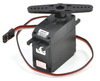
4. Motor control electronics
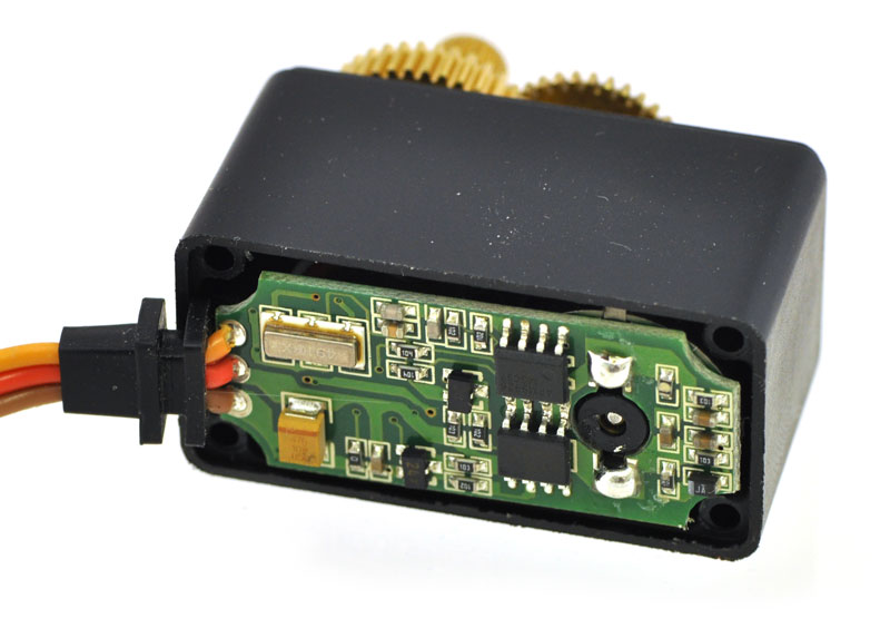 |
This digital servo has the motor soldered directly to main circuit board. |
|---|
Each servo has a little circuit board inside with electronics to accept the command signal from the RC receiver, read the feedback from the position sensor, calculate how much power to give the motor, and drive the motor. (Remember, the servo itself does not have any radio or wireless component; that is all normally handled by the RC receiver.) The electronics subsystem is what allows us to use every servo in basically the same way: we just tell it where to go, and the electronics portion of the servo has to do all of the difficult calculations and power delivery. In the earlier picture, the electronic parts are on a circuit board that has separate wire connections to the motor and potentiometer. The picture to the right shows a servo with a larger circuit board that has the motor soldered directly to the board, without extra wires (the motor is on the right end; the back of the motor and its shaft are visible between the two large solder blobs connecting the motor leads to the circuit board).
As with other components inside the servo, we do not necessarily need to know much about the inner workings of the servo electronics, but there are two broad classes of servo electronics you should know about: analog and digital. The servos that have them are correspondingly called analog and digital servos. The analog servos have a circuit with just analog components (duh!), whereas digital servos have an on-board microcontroller. Digital servos are more expensive, and they are supposed to offer higher performance in terms of speed and accuracy (holding the target position better). Some digital servos also allow some of their internal parameters to be modified to better match the application of the servo. However, the ultimate performance of a digital servo depends on how it is programmed, and it’s certainly possible to make a digital servo perform worse than an analog one. An important point to keep in mind is that both digital and analog servos should be interchangeable in normal applications, so a receiver or servo controller doesn’t know or care if it is controlling an analog or a digital servo. (If you do have a problem with a digital servo and an analog one works in its place, you probably have a power limitation. Digital servos tend to generally have higher performance, and that requires more power.)
Conclusion (for now)
At this point, I hope you have an idea of where servos fit into a typical RC application and some understanding of the basics of the servo itself. Next time, I’ll address the somewhat common mistake of calling servos “servo motors”.
-
Introduction to servos
- 14 January 2011Hobby servos are small, modular actuators developed by the radio control (RC) hobby industry for remote manipulation of everything from miniature...
-

Why we don't have comments on our product pages
- 25 January 2011A customer recently wrote: “I think you really need to add comments from users under each product (like sparkfun does). Makes it easy to review...
2 comments


Post a comment


Home | Forum | Blog | Support | Ordering Information | Lists | Distributors | BIG Order Form | About | Contact
© 2001–2025 Pololu Corporation


