
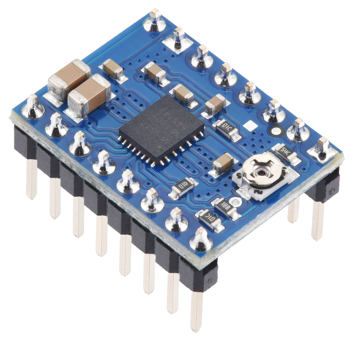
This is a merged information page for Item #5691.
View normal product page.
Pololu item #:
5691
Brand:
Pololu
Status:
Active and Preferred

This version of our MP6603 Stepper Motor Driver Carrier ships with male header pins installed, so no soldering is required to use it with an appropriate 16-pin socket or solderless breadboard. Please see the MP6603 Stepper Motor Driver Carrier product page for more information about the driver.
Alternatives available with variations in these parameter(s): header pins soldered? Select variant…
 Compare all products in MP6603 Stepper Motor Driver Carriers or 16-pin Stepper Motor Drivers.
|
MP6603 Stepper Motor Driver Carrier (Soldered Header Pins). |
|---|
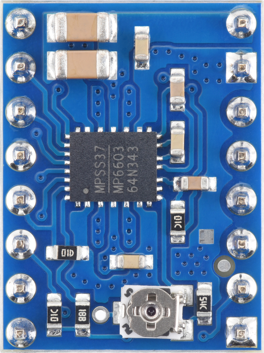 |
MP6603 Stepper Motor Driver Carrier (Soldered Header Pins), top view. |
|---|
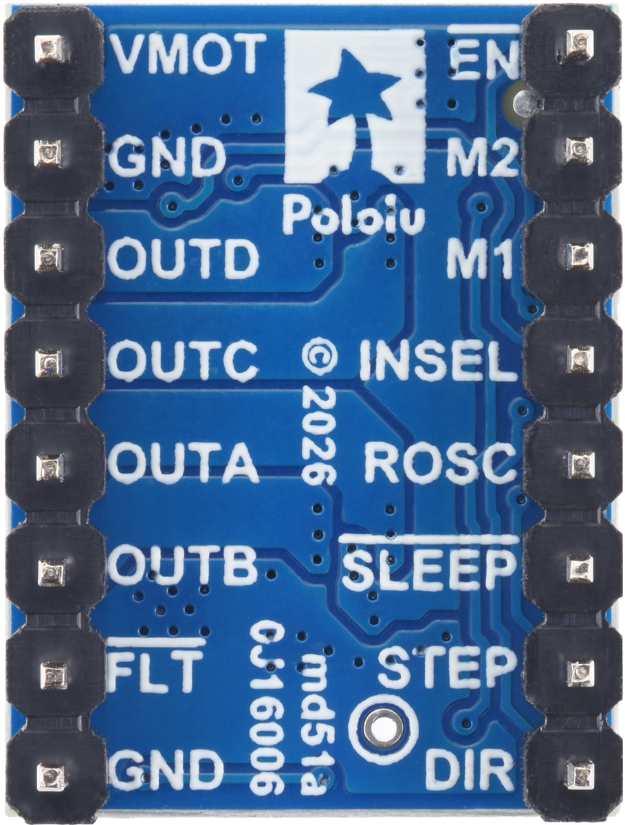 |
MP6603 Stepper Motor Driver Carrier (Soldered Header Pins), bottom view. |
|---|
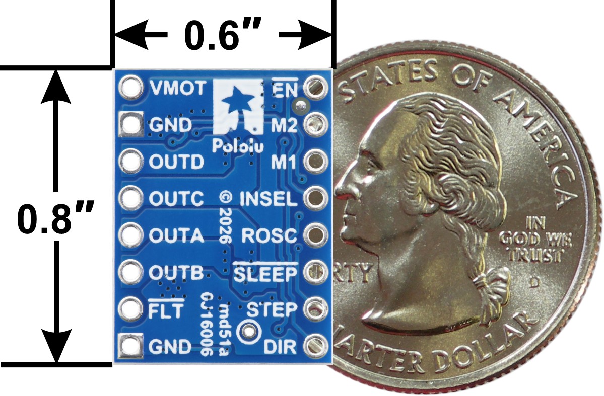 |
MP6603 Stepper Motor Driver Carrier, bottom view with dimensions. |
|---|
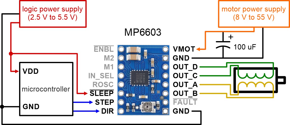 |
Minimal wiring diagram for connecting a microcontroller to an MP6603 Stepper Motor Driver Carrier (full-step mode). |
|---|
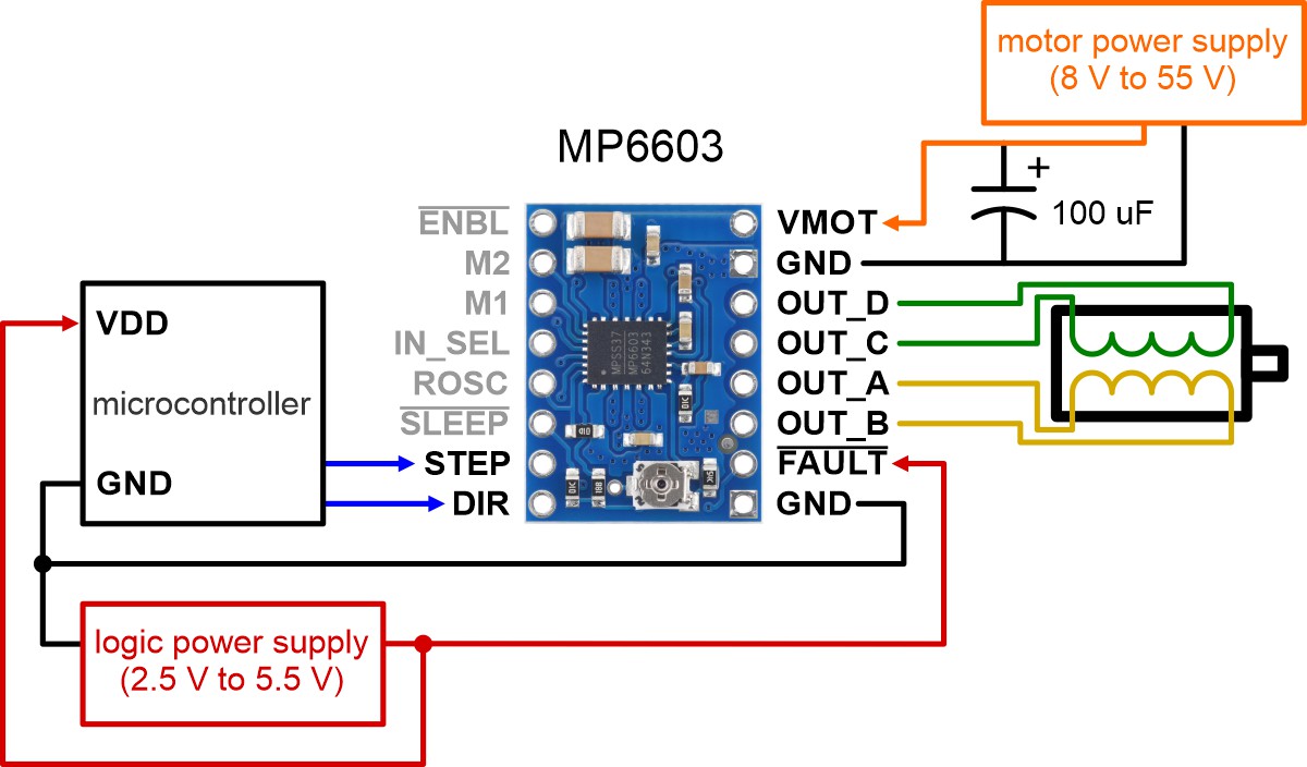 |
Alternative minimal wiring diagram for connecting a microcontroller to an MP6603 Stepper Motor Driver Carrier (full-step mode). |
|---|
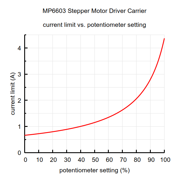 |
Current limit vs. potentiometer setting for the MP6603 Stepper Motor Driver Carrier. |
|---|
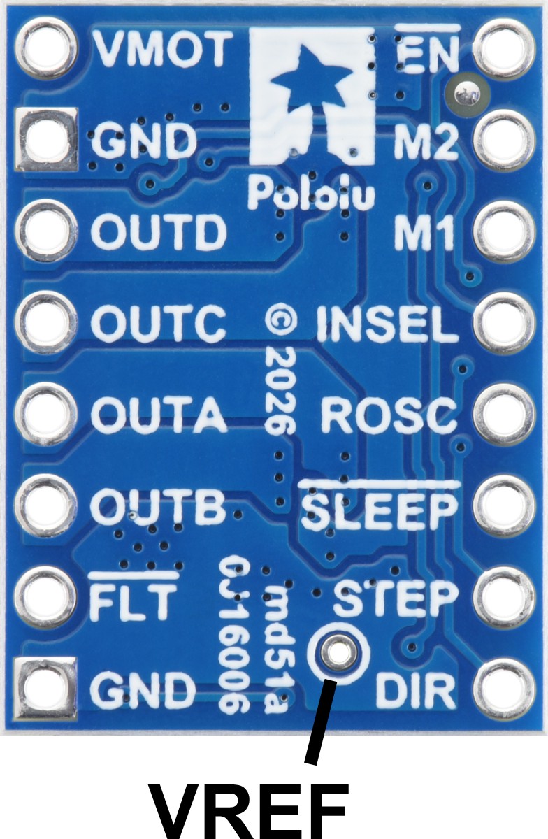 |
VREF pin on the MP6603 Stepper Motor Driver Carrier. |
|---|
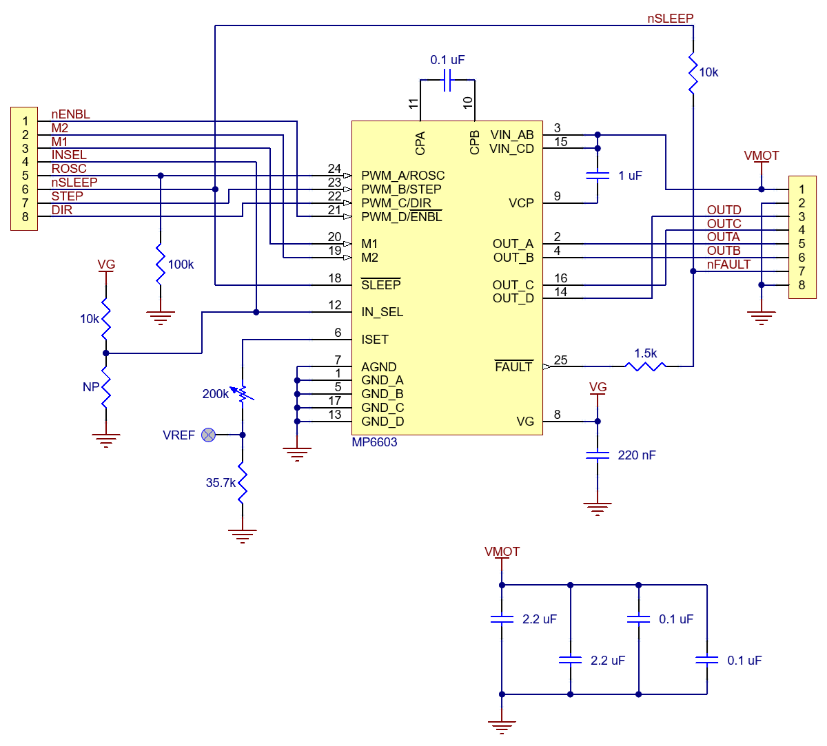 |
Schematic diagram of the MP6603 Stepper Motor Driver Carrier. |
|---|
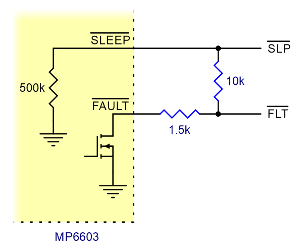 |
Schematic of nSLEEP and nFAULT pins on MP6603 carrier. |
|---|
This version of our MP6603 Stepper Motor Driver Carrier ships with male header pins installed as shown in the main product picture, so no soldering is required to use it with an appropriate 16-pin socket or solderless breadboard. Please see the MP6603 Stepper Motor Driver Carrier product page for more information about the driver.
| Size: | 0.6″ × 0.8″ |
|---|---|
| Weight: | 2.3 g |
| Minimum operating voltage: | 8 V |
|---|---|
| Maximum operating voltage: | 55 V |
| Continuous current per phase: | 2 A1 |
| Maximum current per phase: | 4 A2 |
| Minimum logic voltage: | 2 V3 |
| Maximum logic voltage: | 6 V4 |
| Microstep resolutions: | full, 1/2, 1/4, and 1/8 |
| Current limit control: | potentiometer |
| Reverse voltage protection?: | N |
| Header pins soldered?: | Y |
| PCB dev codes: | md51a |
|---|---|
| Other PCB markings: | 0J16006 |
This DXF drawing shows the locations of all of the board’s holes.
Yes. To avoid damaging your stepper motor, you want to avoid exceeding the rated current, which is 600 mA in this instance. All of our stepper motor drivers let you limit the maximum current, so as long as you set the limit below the rated current, you will be within spec for your motor, even if the voltage exceeds the rated voltage. The voltage rating is just the voltage at which each coil draws the rated current, so the coils of your stepper motor will draw 600 mA at 3.9 V. By using a higher voltage along with active current limiting, the current is able to ramp up faster, which lets you achieve higher step rates than you could using the rated voltage.
If you do want to use a lower motor supply voltage for other reasons, consider using our DRV8834 or STSPIN-220 low-voltage stepper motor drivers.
No blog posts to show.