

This is a merged information page for Item #3150.
View normal product page.
Pololu item #:
3150
Brand:
Pololu
Status:
Active and Preferred

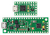
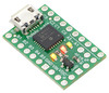
The P-Star 25K50 Micro is a tiny programmable module featuring Microchip’s PIC18F25K50 microcontroller. It packs a Micro-USB interface and 19 digital input/output pins onto a board measuring only 1″ × 0.6″ and ships preloaded with a USB bootloader, so no external programmer is required.
 Compare all products in P-Star Programmable Controllers.
|
P-Star 25K50 Micro. |
|---|
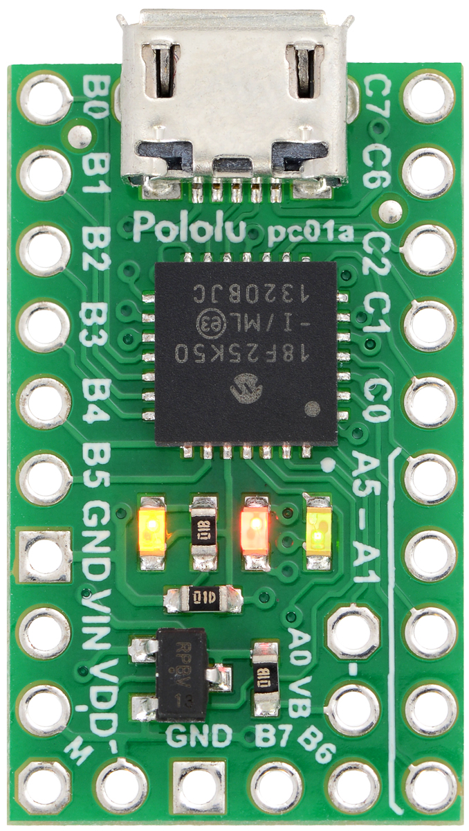 |
P-Star 25K50 Micro, top view. |
|---|
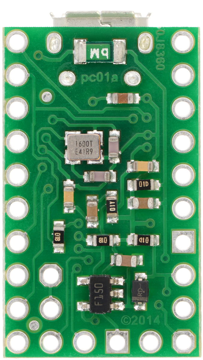 |
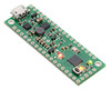
P-Star 25K50 Micro, bottom view. |
|---|
 |
The P-Star 25K50 Micro with soldered headers and connected USB cable. |
|---|
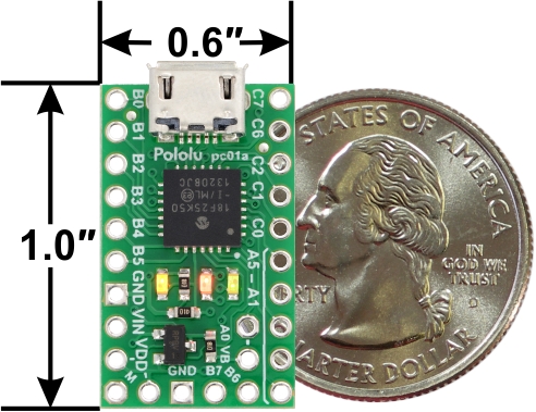 |
P-Star 25K50 with U.S. quarter for size reference. |
|---|
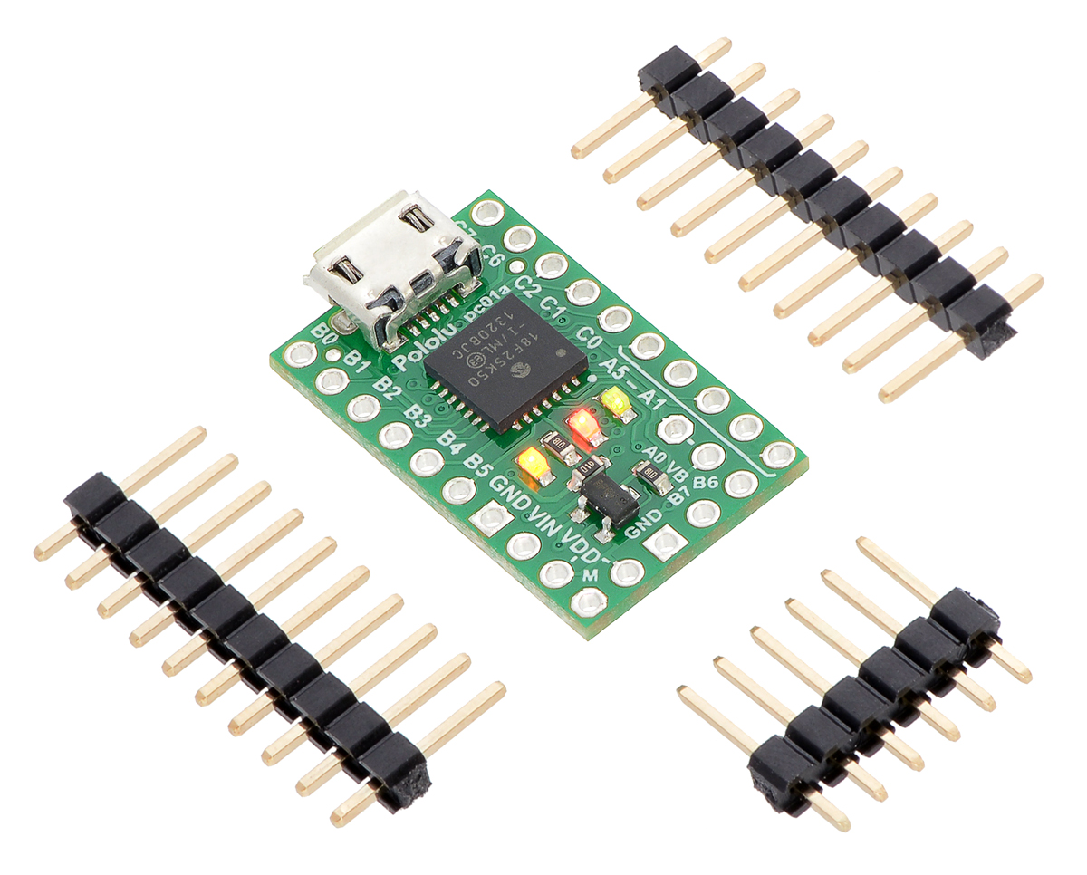 |
P-Star 25K50 Micro with included optional headers. |
|---|
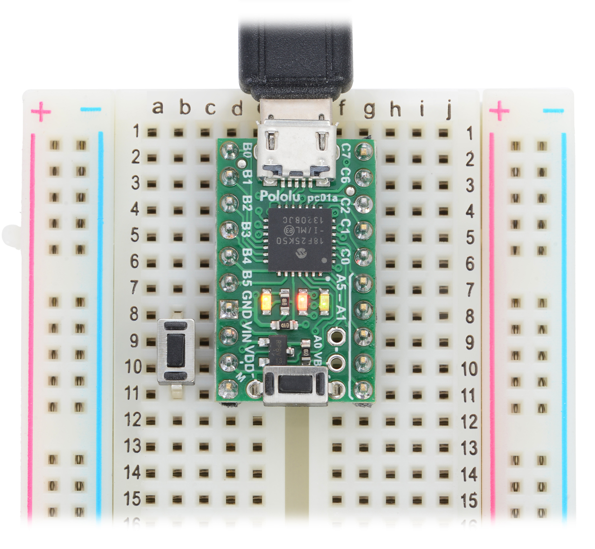 |
P-Star 25K50 Micro on a breadboard with a reset button (left) and a bootloader button (on-board). |
|---|
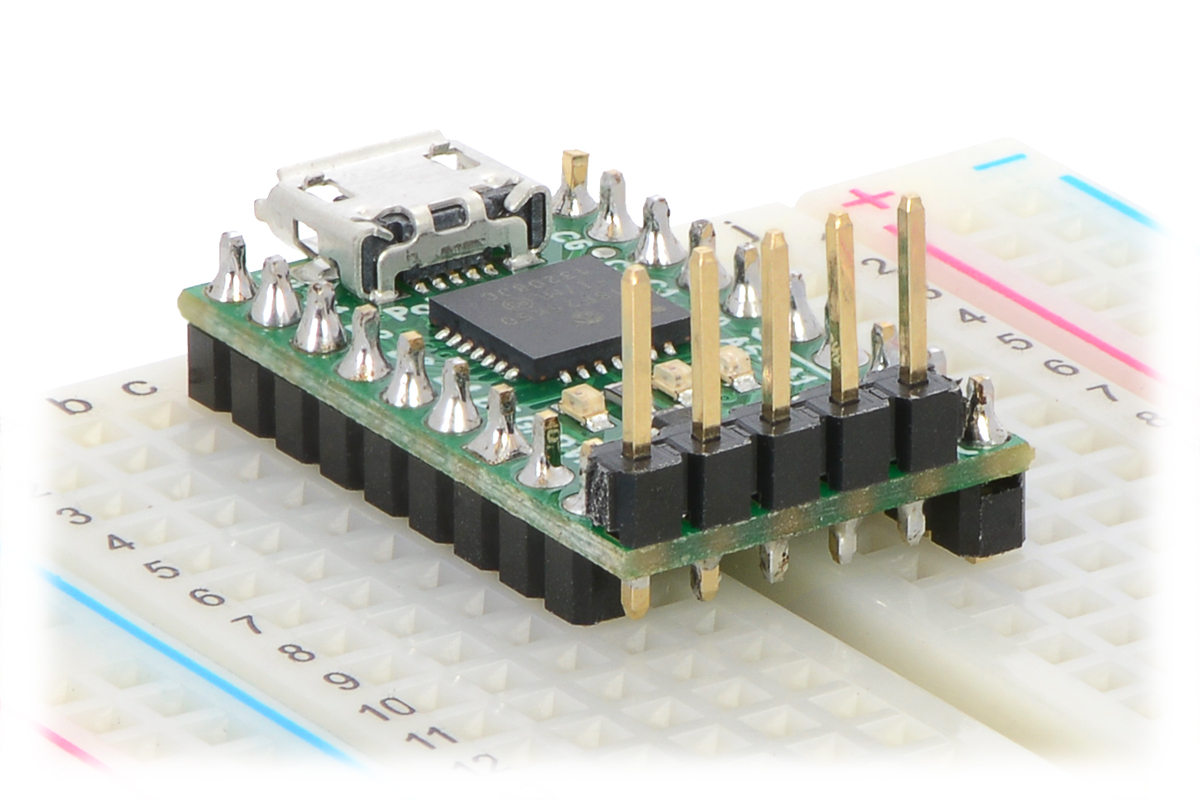 |
The P-Star 25K50 Micro with a vertical 5-pin programming header installed. |
|---|
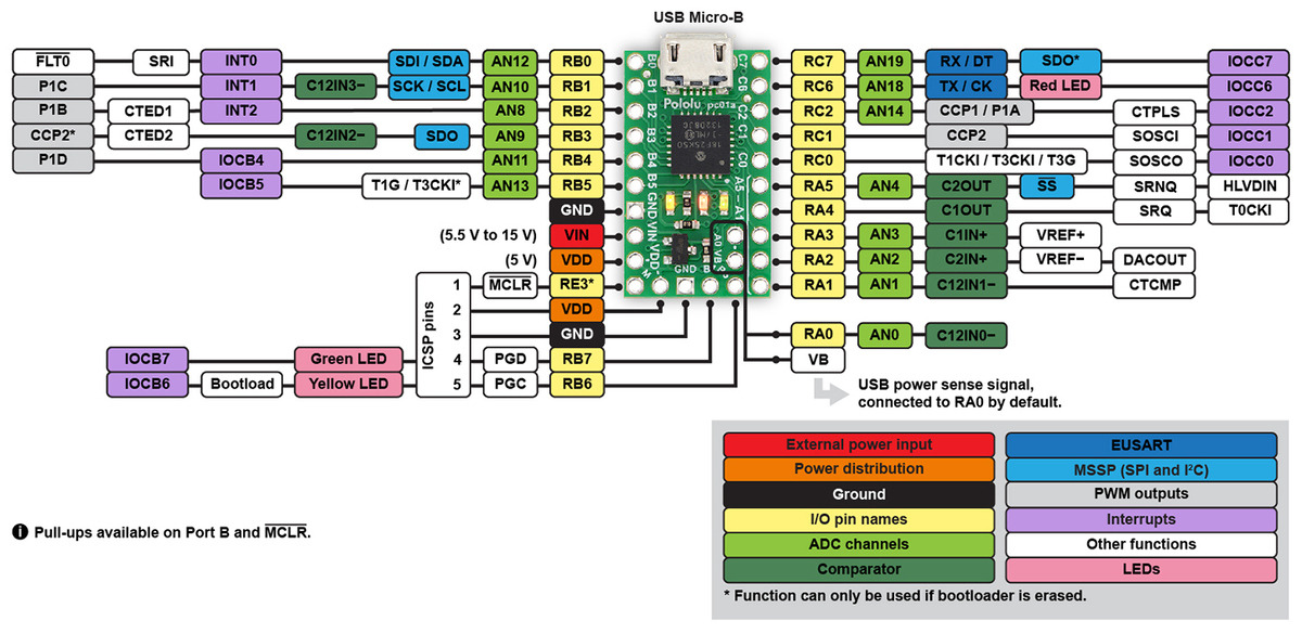 |
P-Star 25K50 Micro pinout diagram. |
|---|
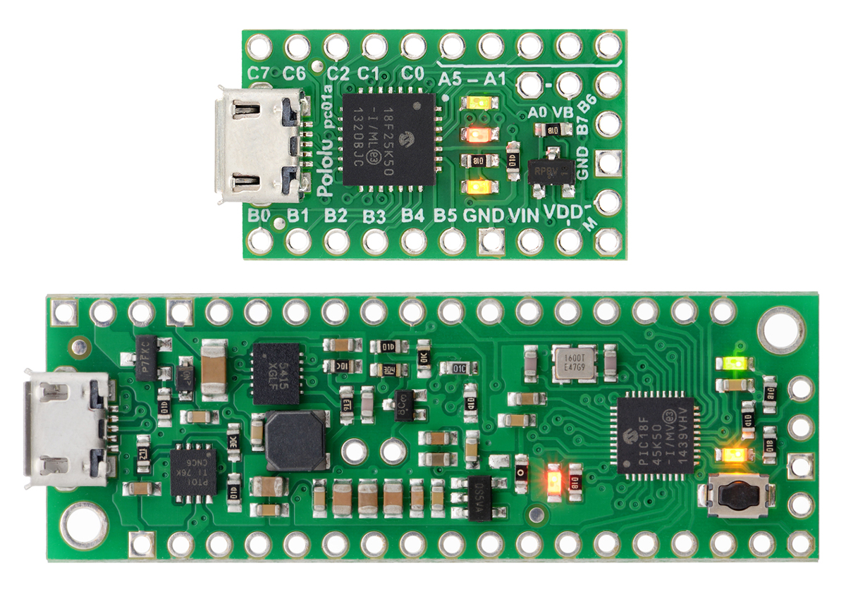 |
P-Star 25K50 Micro (top) and P-Star 45K50 Mini SV (bottom). |
|---|
|
P-Star 25K50 with U.S. quarter for size reference. |
|---|
The Pololu P-Star 25K50 Micro is a general-purpose programmable module based on Microchip’s PIC18F25K50 microcontroller, which has 32 KB of flash program memory, 2 KB of RAM, and built-in USB functionality. On-board features of the P-Star (abbreviated P*) include a 16 MHz crystal, a USB Micro-B connector, and three user-controllable indicator LEDs. A voltage regulator and power selection circuit allow the board to be powered from either USB or an external 5.5 V to 15 V source, while a resettable PTC fuse on the USB VBUS supply and reverse protection on VIN help protect it from accidental damage. The board ships with a USB bootloader that makes it easy to program the PIC microcontroller without using an external programmer.
Our comprehensive user’s guide provides the basics you need to get started with the P-Star 25K50 Micro as well as detailed technical information.
This product requires a USB A to Micro-B cable (not included) to connect to a computer.
|
P-Star 25K50 Micro, bottom view. |
|---|
|
P-Star 25K50 Micro, top view. |
|---|
|
P-Star 25K50 Micro pinout diagram. |
|---|
This diagram identifies the I/O and power pins on the P-Star 25K50 Micro. The diagram is also available as a printable PDF (161k pdf). For more information about the PIC18F25K50 microcontroller and its peripherals, see Microchip’s PIC18F25K50 documentation.
Two 1×10-pin breakaway 0.1″ male headers and one 1×6-pin breakaway 0.1″ male header are included with the P-Star 25K50 Micro. These header pins can be soldered in to use the board with perfboards, breadboards, or 0.1″ female connectors.
|
|
| Size: | 0.6″ × 1.05″ × 0.18″1 |
|---|---|
| Weight: | 1.3 g2 |
| Processor: | PIC18F25K50 |
|---|---|
| RAM size: | 2 Kbytes |
| Program memory size: | 32 Kbytes3 |
| Motor channels: | 0 |
| User I/O lines: | 194 |
| Minimum operating voltage: | 5.5 V |
| Maximum operating voltage: | 15 V |
| Logic voltage: | 5 V |
| Reverse voltage protection?: | Y5 |
| External programmer required?: | N |
| PCB dev codes: | pc01a |
|---|
User’s manual for the Pololu P-Star programmable modules.
Printable pinout diagram of the P-Star 25K50 Micro.
Printable schematic of the P-Star 25K50 Micro.
Printable dimension diagram of the P-Star 25K50 Micro.
This DXF drawing shows the locations of all of the board’s holes.
Microchip’s product page for the PIC18F25K50, with links to its datasheet and other resources.
MPLAB X is a free IDE from Microchip for programming their PIC microcontrollers. It runs on Windows, Max OS X, and Linux. MPLAB X comes with the a simulator and the MPASM assembler. It works well with the MPLAB XC Compilers and the PICkit 3.
The MPLAB XC Compilers from Microchip are a family of C compilers for PIC MCUs. The compilers are free to use, but paid versions are available that provide better optimizations.
A collection example code and libraries for the P-Star.
Microchip’s PICkit 3 programmer is a low-cost hardware debugger and programmer for PIC microcontrollers.
SDCC is a free and open source compiler that supports many types of microcontrollers, including PIC MCUs that use the PIC18 architecture. The PIC18s are called PIC16 in the SDCC documentation and command-line interface because the instructions are 16 bits wide. As of August 2014, the SDCC manual states that the support for these PIC microcontrollers “is not yet mature and still lacks many features”.
A BASIC compiler that targets PIC microcontrollers.
M-Stack is an open source USB Stack from Signal 11 Software for Microchip PIC microcontrollers.
The RPicSim library provides an interface to the MPLAB X PIC simulator that allows you to write simulator-based automated tests of PIC firmware. RPicSim is written in the Ruby language and runs on JRuby.
This bootloader can run on the P-Star 25K50. It acts as a USB mass storage device and allows the P-Star to be programmed by copying a HEX file onto it.
No FAQs available.
I am excited to announce our new product, the Pololu P-Star 45K50 Mini SV, which is the second member of our P-Star family of programmable...
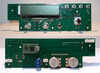
Edward Cholakian (call sign KB1OIE) makes and sells a Ten-Tec 1254 Receiver Display Upgrade Kit that is designed to upgrade a Ten-Tec 1254 shortwave...
RPicSim is an open source software library written in Ruby that provides an interface to the MPLAB X PIC simulator and allows you to write...
We just released the P-Star 25K50 Micro, a programmable breakout board for Microchip’s PIC18F25K50 microcontroller. Although we have been using PIC...