This is a merged information page for Item #2587.
View normal product page.
Pololu item #:
2587
Brand:
Pololu
Status:
Active and Preferred

This compact board breaks out the pins of a microSD card connector necessary to interface with the card through SPI (Serial Peripheral Interface), and it can be directly integrated into 5 V systems thanks to its on board 3.3 V regulator and level shifting circuits. The 0.1″ pin spacing allows compatibility with standard perfboards, solderless breadboards, and 0.1" connectors.
 Compare all products in Electronics Prototyping.
|
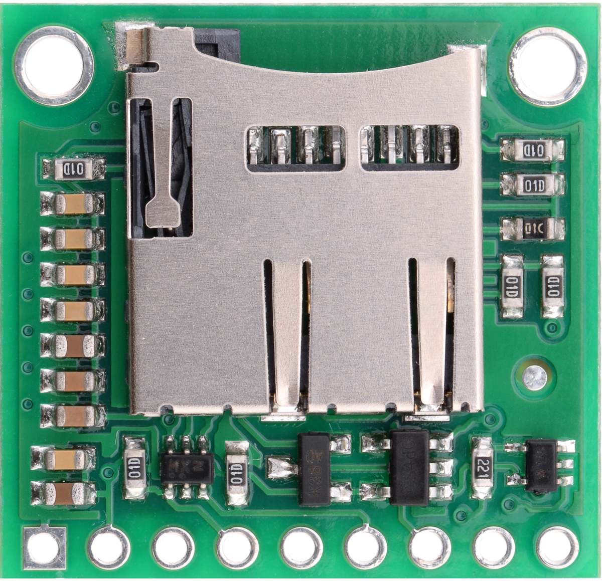
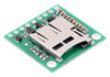
Breakout Board for microSD Card with 3.3V Regulator and Level Shifters |
|---|
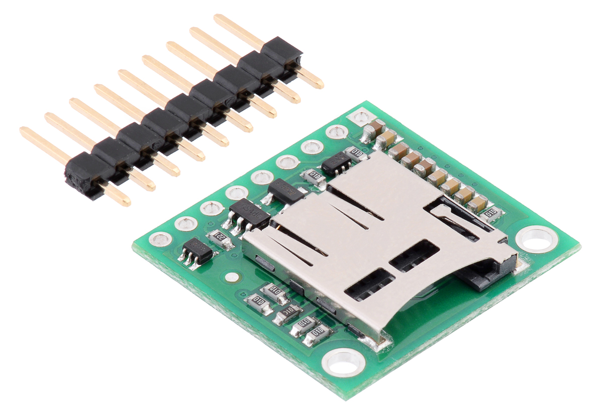 |
Breakout Board for microSD Card with 3.3V Regulator and Level Shifters with included header pins. |
|---|
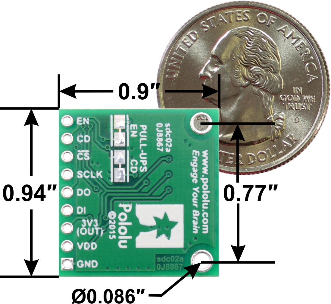 |
Breakout Board for microSD Card with 3.3V Regulator and Level Shifters, bottom view with dimensions. |
|---|
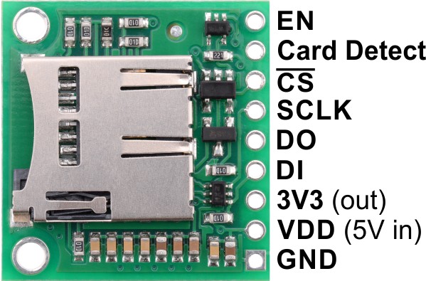 |
Breakout Board for microSD Card with 3.3V Regulator and Level Shifters, labeled top view. |
|---|
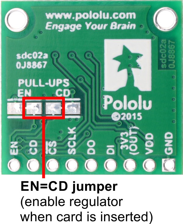 |
Breakout Board for microSD Card with 3.3V Regulator and Level Shifters, bottom view with the EN=CD jumper labeled. |
|---|
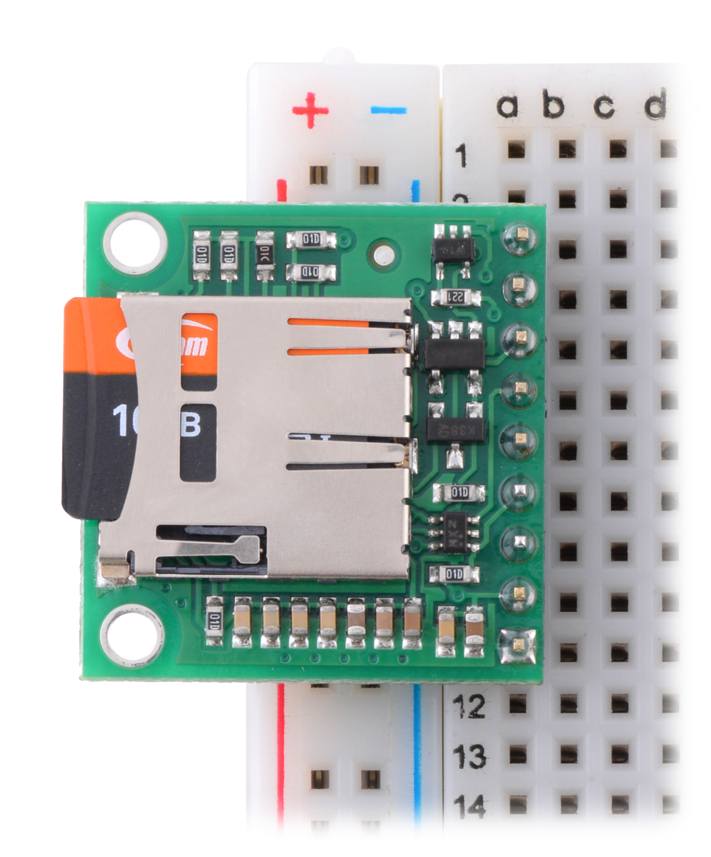 |
Breakout Board for microSD Card with 3.3V Regulator and Level Shifters plugged into a breadboard with microSD card (not included) inserted. |
|---|
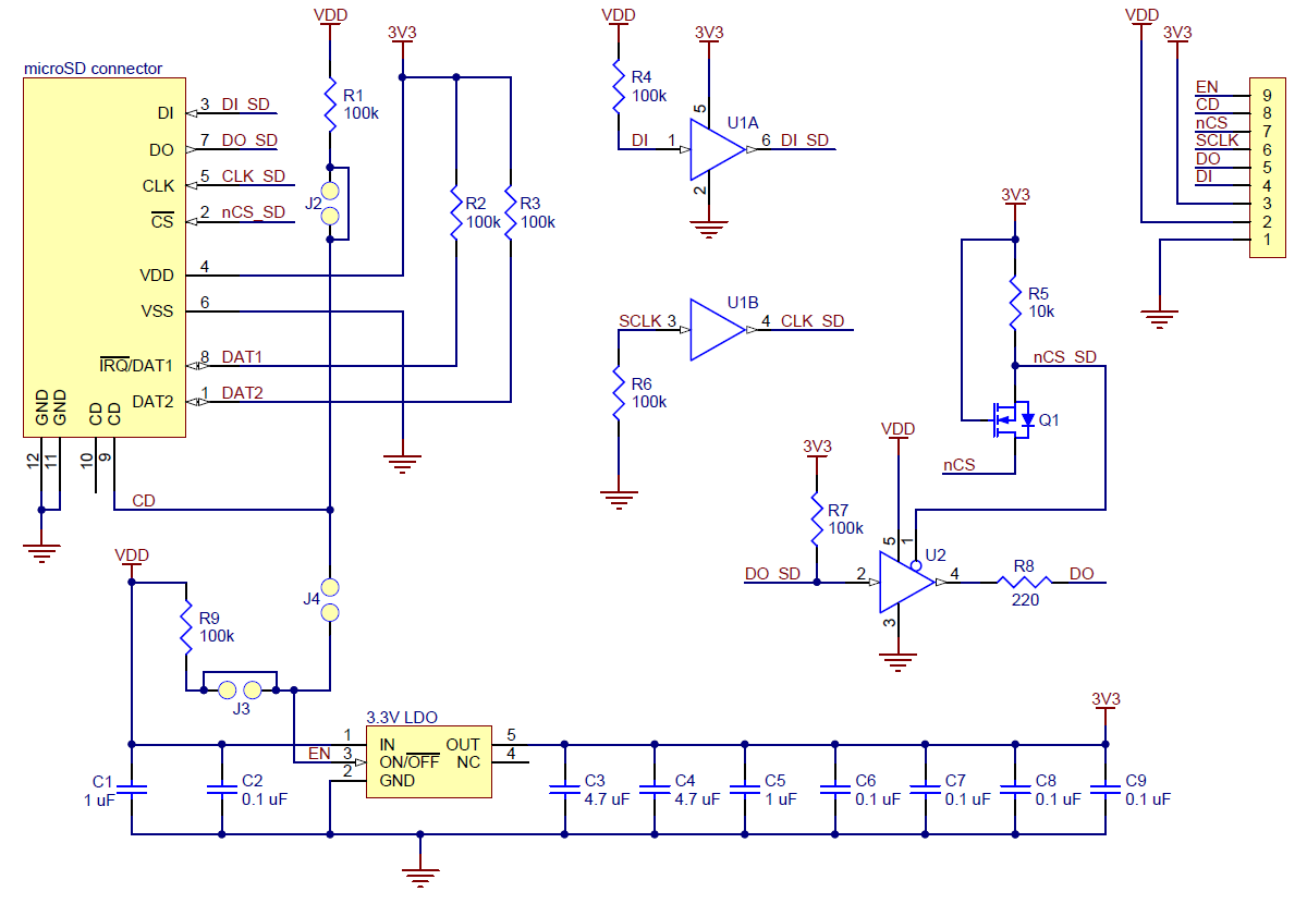 |
Breakout Board for Micro SD Card with 3.3V Regulator and Level Shifter schematic diagram. |
|---|
|
This carrier board makes it easy to interface a microSD memory card (originally known as TransFlash) with an SPI-capable microcontroller, offering a convenient and inexpensive way to add gigabytes of non-volatile storage to an embedded project. It includes a 3.3 V regulator and level shifters on the four SPI lines, enabling direct integration into 5 V systems, and it provides access to the all of the connections through single 1×9 row of 0.1″-spaced through-holes. A breakaway 0.1″ male header strip is included, which can be soldered in to use the board with breadboards, perfboards, or 0.1″ female connectors, and the board has two mounting holes for #2 or M2 screws.
|
|
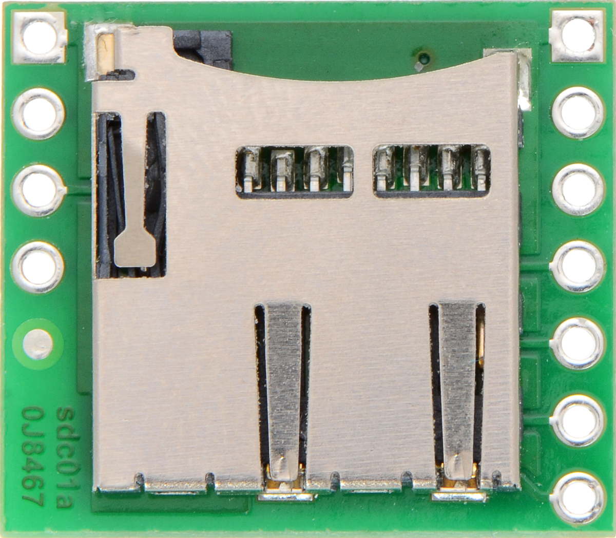
For 3.3 V projects, we carry a smaller Breakout Board for MicroSD Card without the 3.3 V regulator, level shifters, and mounting holes. This more basic module (shown in the right picture below) breaks out all of the microSD pins (including the ones used for the SD bus mode interface) rather than just the SPI-interface pins.
|
|
For a microSD socket and user-programmable microcontroller on a single board, consider our A-Star 32U4 Prime controllers, which essentially use the same level-shifting circuits to interface a microSD card with an Arduino-compatible ATmega32U4 MCU running at 5 V.
Since many microcontrollers have built-in SPI interfaces, most hobbyist projects communicate with Secure Digital cards in SPI bus mode; this is the only mode supported by this board. (The alternative SD bus mode is proprietary, and a license from the SD Association is required for access to the full specifications.) The pins on this board are labeled according to their functions in SPI mode.
|
| Pin | Description | ||
|---|---|---|---|
| EN | Enables the 3.3 V regulator. This pin is pulled-up to VDD through a 100 kΩ resistor to enable the regulator by default. | ||
| CD | Card detect. This pin is pulled up to VDD through a 100 kΩ resistor. When a card is inserted, it is high; when no card is inserted, it is shorted to ground. | ||
| CS | Chip select (must be driven low to talk to the microSD card) | ||
| SCLK | SPI clock | ||
| DO | SPI data out (MISO) level shifted to 5 V | ||
| DI | SPI data in (MOSI) | ||
| 3V3 (OUT) | Output from the 3.3 V regulator | ||
| GND | Power and logic ground | ||
| VDD | Supply voltage (5 V) | ||
The board is powered by applying 5 V to the VDD pin, and all of the logic pins can be interfaced directly with 5 V systems thanks to integrated level shifters. The output of the integrated 3.3 V regulator can be accessed through the 3V3 pin, and the regulator can be disabled to turn off the microSD card and save power by driving the EN pin low.
By default, the EN and CD (Card Detect) pins are each pulled up to VDD through 100 kΩ resistors. However, there are cuttable traces on the underside of the board to allow you to disconnect each pull-up as desired. These traces are located between pairs of pads (labeled “EN” and “CD” on the board’s silkscreen) that can be bridged with solder to reconnect the pull-up resistor. Alternatively, the neighboring EN and CD pads of these surface-mount jumpers (highlighted in the picture below) can be connected if you want the regulator to automatically be enabled when the microSD card is inserted and disabled when it is removed.
|
The SD Association publishes a set of simplified specifications for SD cards containing information on interfacing with them. However, there are a number of ways to get started without understanding the specifications or writing your own code from scratch, since many microcontroller development platforms provide libraries for communicating with SD cards. For example:
|
Breakout Board for Micro SD Card with 3.3V Regulator and Level Shifter schematic diagram. |
|---|
This schematic is also available as a downloadable pdf (106k pdf).
| Size: | 0.94″ × 0.9″ × 0.12″1 |
|---|---|
| Weight: | 1.8 g2 |
| PCB dev codes: | scd02a |
|---|---|
| Other PCB markings: | 0J8867 |
Printable schematic of Breakout Board for Micro SD Card with 3.3V Regulator and Level Shifters.
This DXF drawing shows the locations of all of the board’s holes.
The SD Association’s simplified standard specifications for SD cards.
No FAQs available.
In September of last year, we started carrying our Breakout Board for microSD Card, which was the first board that I ever designed and routed here...