

This is a merged information page for Item #2357.
View normal product page.
Pololu item #:
2357
Brand:
Unspecified
Status:
Active and Preferred

This tiny, cylindrical gearmotor consists of a coreless brushed DC motor and a 26:1 plastic planetary gearbox. The entire assembly has a diameter of just 6 mm (0.24″) and an extremely light weight of 1.2 g (0.042 oz), making it a great actuator for miniature robots and very small mechanisms.
Key specs at 6 V: 2500 RPM and 35 mA free-run, 1.5 oz-in (0.1 kg-cm) and 400 mA stall.
Alternatives available with variations in these parameter(s): gear ratio Select variant…
 Compare all products in Plastic DC Gearmotors.
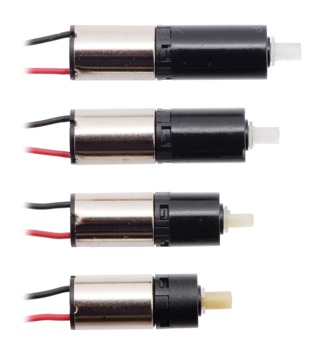 |
Sub-micro plastic planetary gearmotors; from top to bottom: 700:1, 136:1, 26:1, 5.1:1. |
|---|
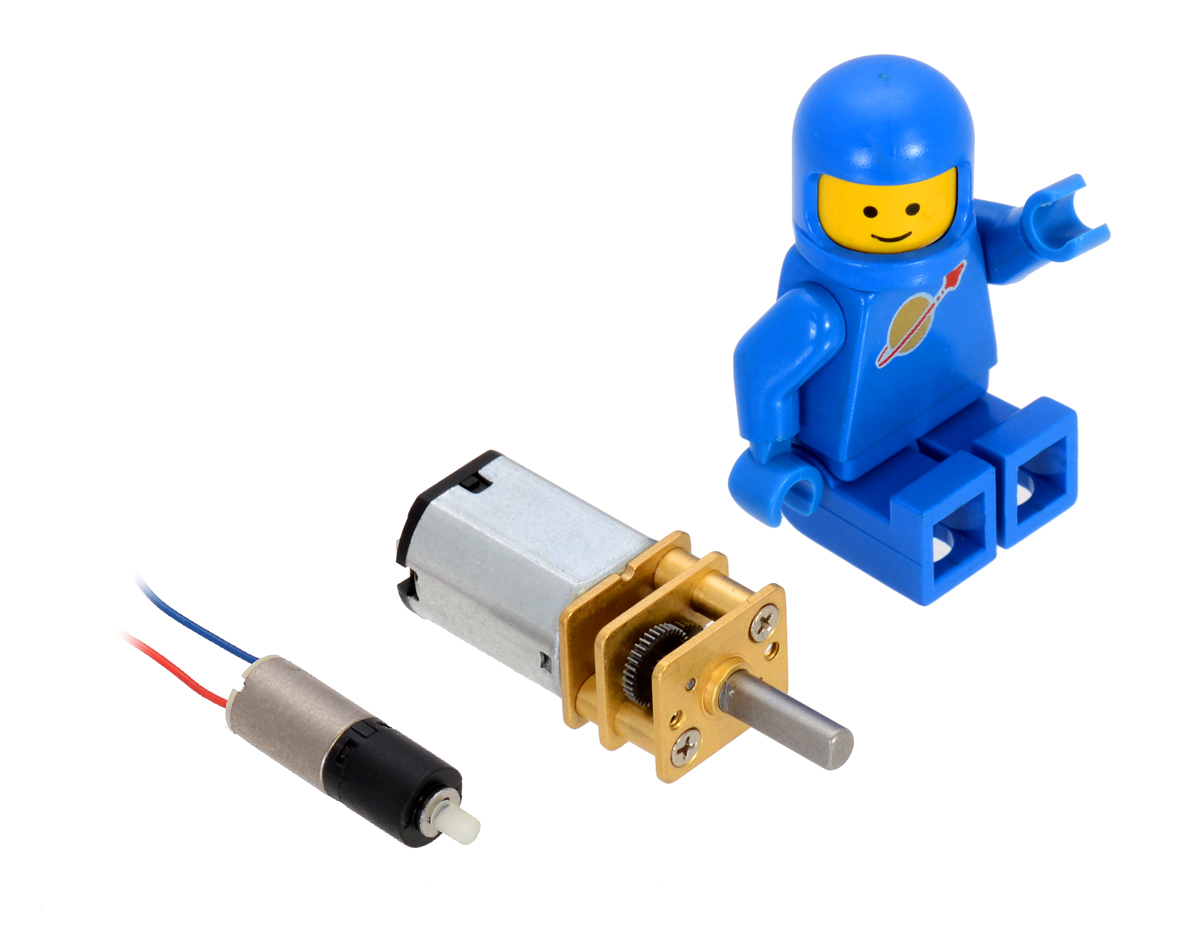 |
26:1 sub-micro plastic planetary gearmotor next to a Micro Metal Gearmotor and a LEGO Minifigure for size reference. |
|---|
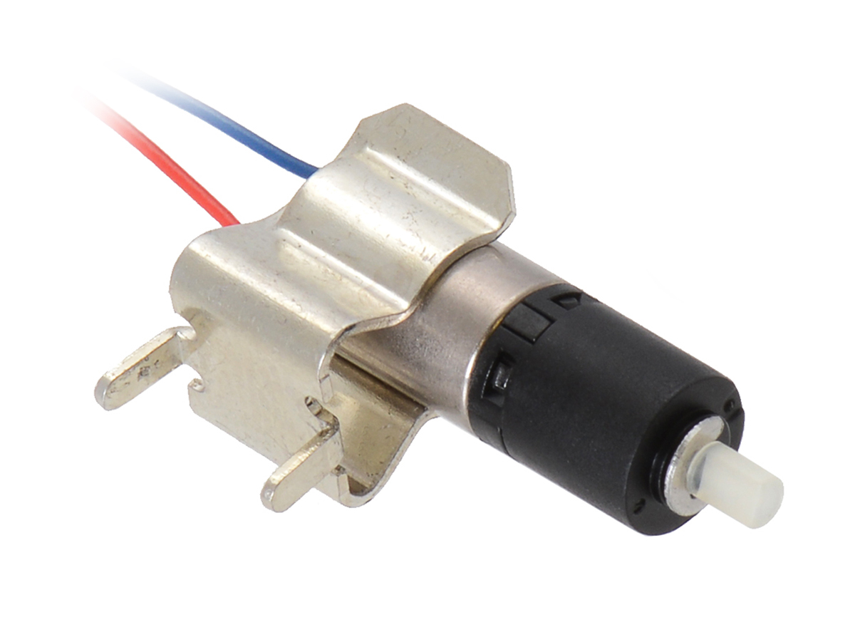 |
26:1 sub-micro plastic planetary gearmotor being held by a 1/4″ (6 mm) fuse clip. |
|---|
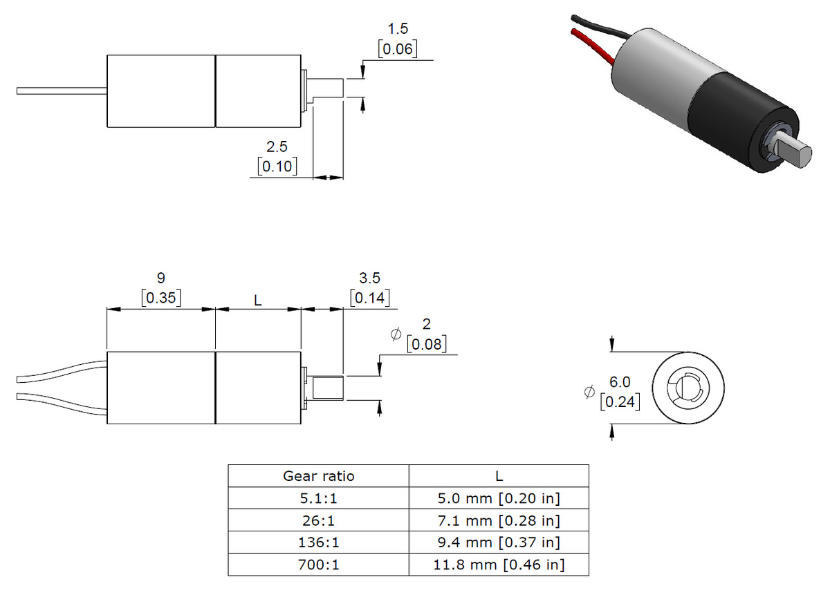 |
Dimensions of the Sub-Micro Plastic Planetary Gearmotors. Units are mm over [inches]. |
|---|
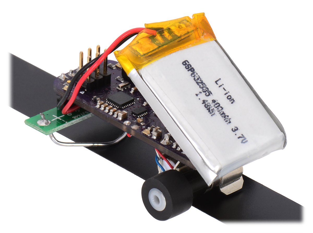 |
This line follower uses gearmotors and wheels very similar to our sub-micro plastic planetary gearmotors and 14mm wheels. |
|---|
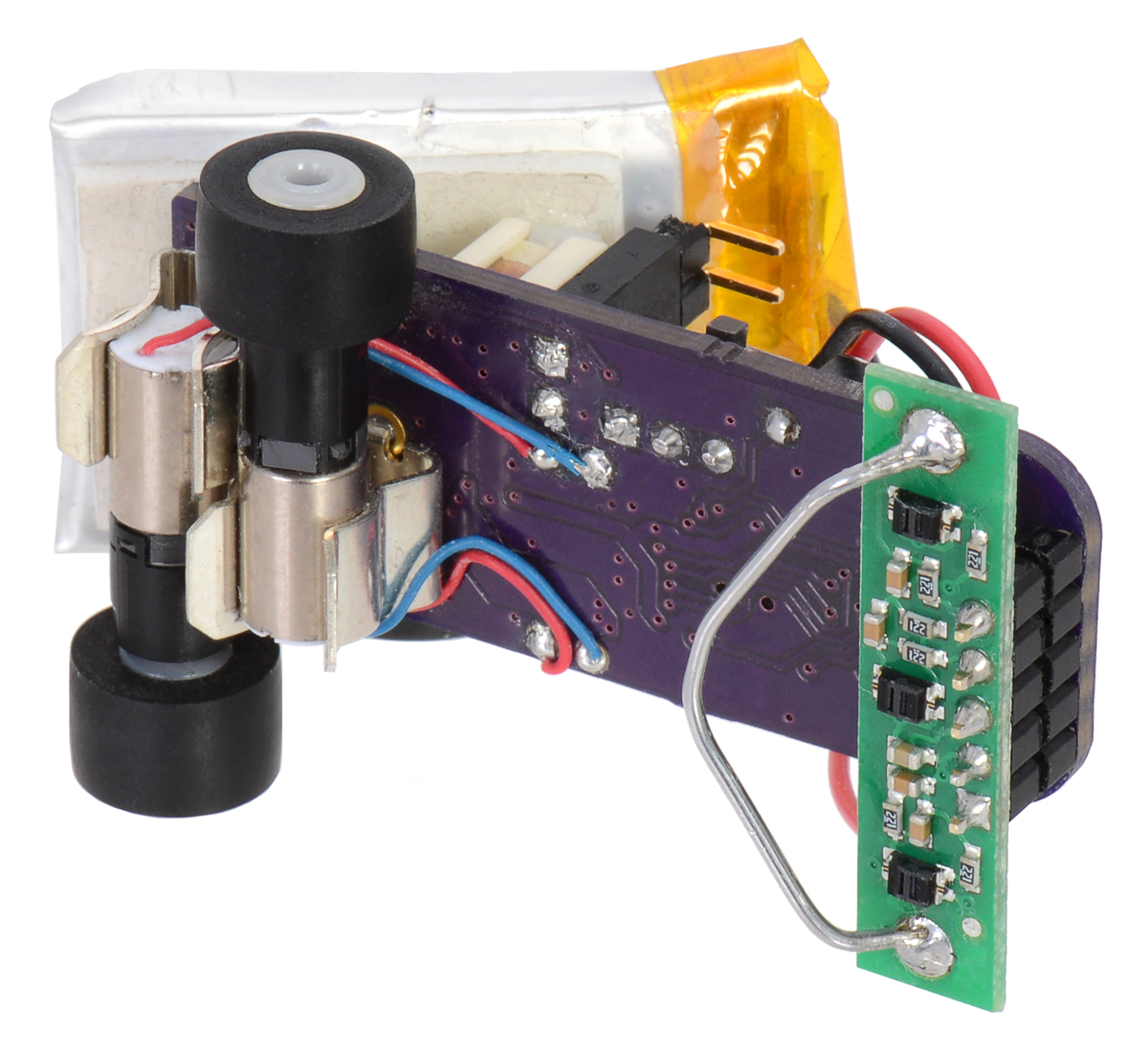 |
This line follower uses gearmotors and wheels very similar to our sub-micro plastic planetary gearmotors and 14mm wheels. |
|---|
|
26:1 sub-micro plastic planetary gearmotor next to a Micro Metal Gearmotor and a LEGO Minifigure for size reference. |
|---|
|
Sub-micro plastic planetary gearmotors; from top to bottom: 700:1, 136:1, 26:1, 5.1:1. |
|---|
These tiny brushed DC gearmotors have a diameter of just 6 mm and weigh just over a gram, which makes them great actuators for miniature robots and very small mechanisms. They consist of a coreless motor fastened to a planetary gearbox by a small clip. The gears are made from liquid crystal polymers (LCPs), and gearbox’s nylon output shaft is compatible with our 14 mm wheels. Several gear ratios are available:
Note: Stalling or overloading gearmotors can greatly decrease their lifetimes and even result in immediate damage. For these gearboxes, the recommended upper limit for instantaneous torque is 3.5 oz-in (250 g-cm); we strongly advise keeping applied loads well under this limit. Stalls can also result in rapid (potentially on the order of seconds) thermal damage to the motor windings and brushes; a general recommendation for brushed DC motor operation is 25% or less of the stall current.
The intended nominal operating voltage for these motors is 3 V to 6 V, though in general, these kinds of motors can be used at voltages outside this range (rotation typically starts between 0.2 V and 0.3 V). Lower voltages might not be practical, and higher voltages could start negatively affecting the life of the motor. When operating at 3 V, the free-run speed, stall torque, and stall current will all be approximately half of what they are at 6 V as these specifications scale roughly linearly with voltage.
Since the gearmotor’s output shaft is nylon, there can be small variances in the diameter from unit to unit. These variations might cause press-fit attachments like our 14 mm wheel to fit loosely in some instances. If you experience a loose fit, you could try swapping wheels or using a small dab of glue to help hold the wheel on.
The following diagram shows the micro plastic gearmotor dimensions in mm. The planetary gearbox has a D-shaped plastic output shaft, which is 2 mm in diameter with a section that is flattened by 0.5 mm. The “D” portion of the shaft is 2.5 mm long. The motor measures 6 mm in diameter and 9.3 mm in length, and the gearbox length, labeled “L” in the diagram below, depends on the gear ratio.
|
Dimensions of the Sub-Micro Plastic Planetary Gearmotors. Units are mm over [inches]. |
|---|
This dimension diagram is also available as a downloadable PDF (220k pdf).
All versions except 5.1:1 previously shipped with red and blue leads that extended approximately 12.5 cm (5″) from the back of the motor, but we began transitioning to shipping units with shorter red and black leads (approximately 5 cm, or 2″) in November 2019. The 700:1 gear ratio version is still in the process of transitioning, so you could receive either lead length in your order. All other versions are already shipping with the 5 cm leads. These leads are pre-stripped and unterminated (i.e. they do not end in a connector).
We do not have any brackets for this gearmotor, and it does not have any mounting holes, but its compact size makes it easy to fasten with tape or glue. Alternatively, since this gearmotor is nearly the same size as a 1/4″ fuse, it can be mounted using standard 1/4″ (6 mm) fuse clips, which can be found at places like Digi-Key.
|
26:1 sub-micro plastic planetary gearmotor being held by a 1/4″ (6 mm) fuse clip. |
|---|
| Size: | 6D × 16L mm |
|---|---|
| Weight: | 1.2 g |
| Shaft diameter: | 2 mm |
| Gear ratio: | 26:1 |
|---|---|
| No-load speed @ 6V: | 2500 rpm |
| No-load current @ 6V: | 35 mA |
| Stall current @ 6V: | 400 mA |
| Stall torque @ 6V: | 1.5 oz·in |
| Lead length: | 2 in |
This file contains 3D models (in the step file format) of the Sub-Micro Plastic Planetary Gearmotors.
This MATLAB script, written by Ali Asgher Mansoor Habiby, plots speed, power, current draw, and efficiency as they vary with torque when you input the gearmotor specifications. It also prints the resistance of the motor, and the current draw and torque at which maximum efficiency and maximum power occur.
No; the information we have available for this motor can be found on its product page. However, you can approximate various additional motor parameters from the information found in the “Specs” tab.
The electrical resistance of the motor can be approximated by dividing the rated voltage by the stall current (at the rated voltage). The electromotive force constant (Ke) can be approximated by dividing the rated voltage by the free-run speed (at the rated voltage). To approximate the motor torque constant (Kt), you can divide the stall torque by the stall current.
For pretty much any DC motor, the current, speed, power, and efficiency curves as a function of torque will look like those in the graph below (assuming motor voltage and temperature are constant):
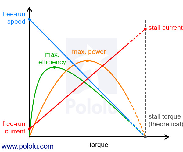 |
The current and speed curves are approximately linear, and the product pages for our motors provide the approximate end points for these lines: (0 torque, no-load current) and (stall torque, stall current) for the red line, and (0 torque, no-load speed) and (stall torque, 0 speed) for the blue line.
The orange output power curve is the product of the speed and the torque, which results in an inverted parabola with its peak at 50% of the stall torque.
The green efficiency curve is the output power divided by the input power, where the input power is current times voltage. The voltage is constant, so you can divide the output power curve by the current line to get the general shape of the efficiency curve, which in turn lets you identify the torque, speed, and current that correspond to max efficiency.
There are many programs out there that you can use to generate these curves. For example, if you have access to MATLAB, you can use this customer-created MATLAB script to generate these motor plots for you from the specifications we provide for each gearmotor.
Note: A good general rule of thumb is to keep the continuous load on a DC motor from exceeding approximately 20% to 30% of the stall torque. Stalling gearmotors can greatly decrease their lifetimes, occasionally resulting in immediate damage to the gearbox or thermal damage to the motor windings or brushes. Do not expect to be able to safely operate a brushed DC gearmotor all the way to stall. The safe operating range will depend on the specifics of the gearmotor itself.

Need a “little” help with your next electronics project? Get it up and running with our sub-micro plastic planetary gearmotors! Measuring a...