

This is a merged information page for Item #1476.
View normal product page.
Pololu item #:
1476
Brand:
SOYO
Status:
Active and Preferred

This NEMA 23-size hybrid stepping motor can be used as a unipolar or bipolar stepper motor and has a 1.8° step angle (200 steps/revolution). Each phase draws 1 A at 5.7 V, allowing for a holding torque of 4 kg-cm (55 oz-in).
 Compare all products in Stepper Motors or NEMA 23 Stepper Motors.
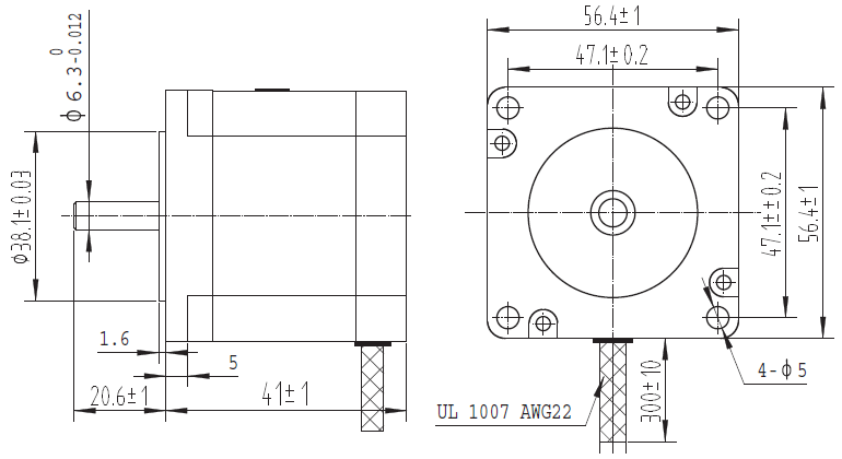 |
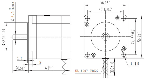
Dimensions (in mm) of 57mm square (NEMA 23) by 41mm unipolar/bipolar stepper motor. |
|---|
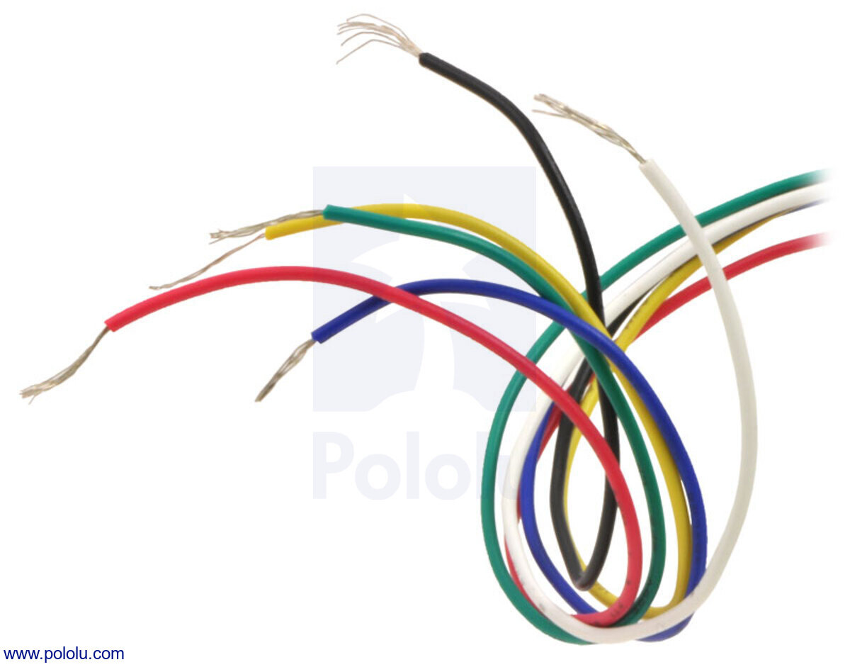 |
6-lead, unipolar/bipolar stepper motor wires are terminated with bare leads. |
|---|
 |
6-lead, unipolar/bipolar stepper motor wiring diagram. |
|---|
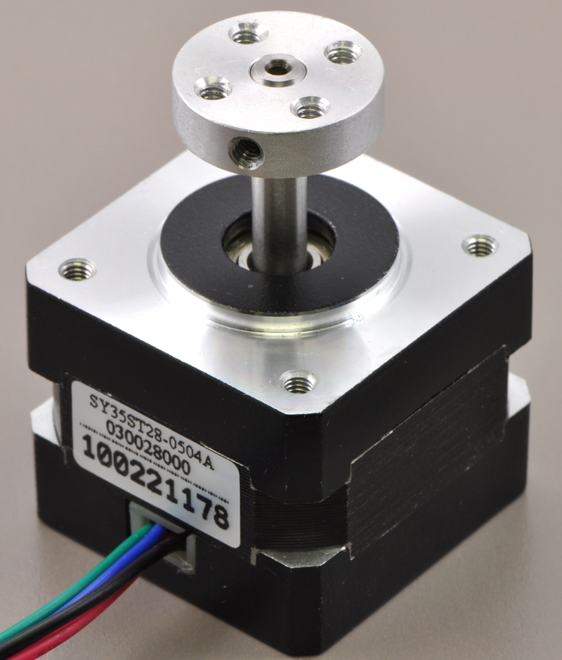 |
5mm Pololu universal aluminum mounting hub on a stepper motor with a 5mm-diameter output shaft. |
|---|
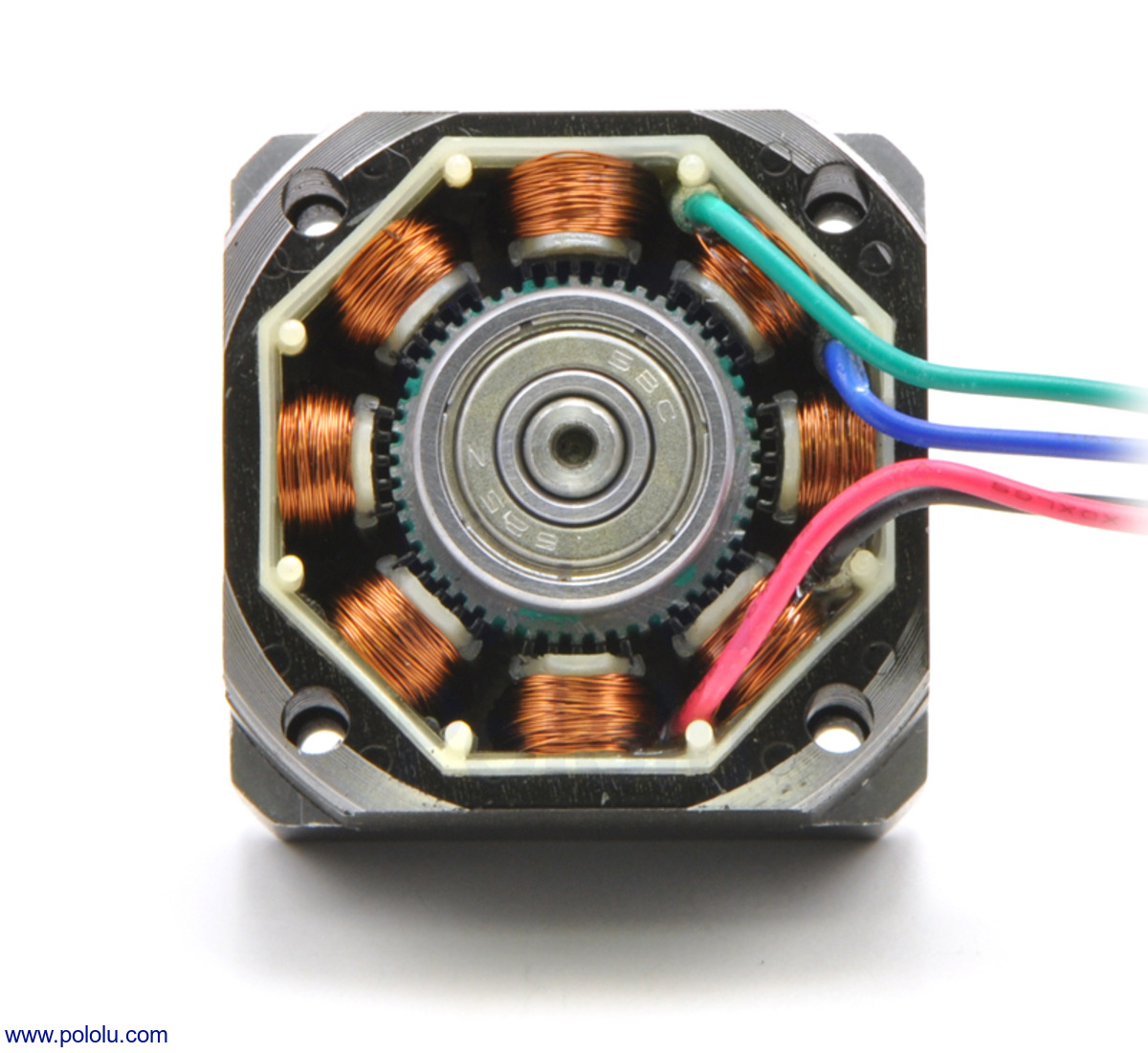 |
The inside of a bipolar stepper motor (SOYO NEMA 14-size). |
|---|
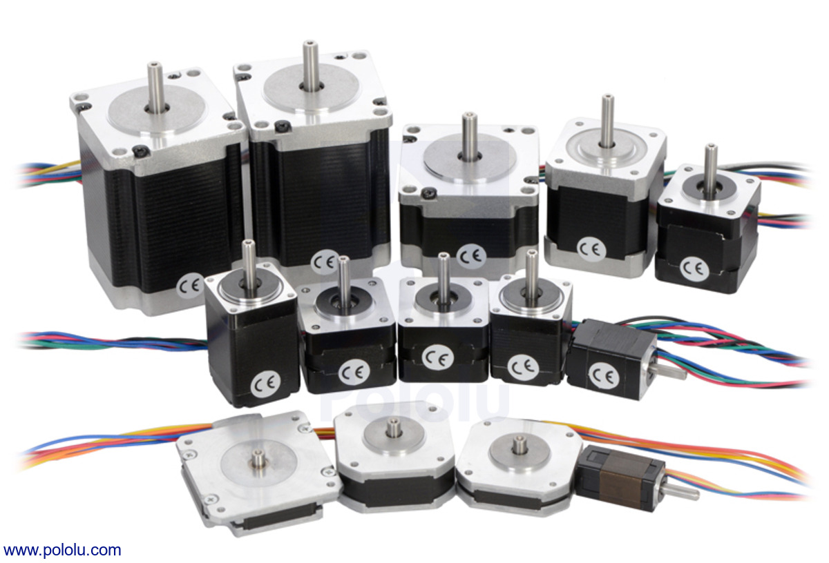 |
Pololu’s assortment of stepper motors. |
|---|
|
6-lead, unipolar/bipolar stepper motor wires are terminated with bare leads. |
|---|
 |
6-lead, unipolar/bipolar stepper motor wiring diagram. |
|---|
This high-torque hybrid stepping motor has a 1.8° step angle (200 steps/revolution). Each phase draws 1 A at 5.7 V, allowing for a holding torque of 4 kg-cm (55 oz-in). The motor has six color-coded wires terminated with bare leads that allow it to be controlled by both unipolar and bipolar stepper motor drivers. When used with a unipolar stepper motor driver, all six leads are used. When used with a bipolar stepper motor driver, the center-tap yellow and white wires can be left disconnected (the red-blue pair gives access to one coil and the black-green pair gives access to the other coil). We recommend using it as a bipolar stepper motor and controlling it with one of our bipolar stepper motor drivers or one of our Tic Stepper Motor Controllers. In particular, the Tics make control easy because they support six different interfaces (USB, TTL serial, I²C, RC, analog voltages, and quadrature encoder) and are configurable over USB with our free configuration utility.
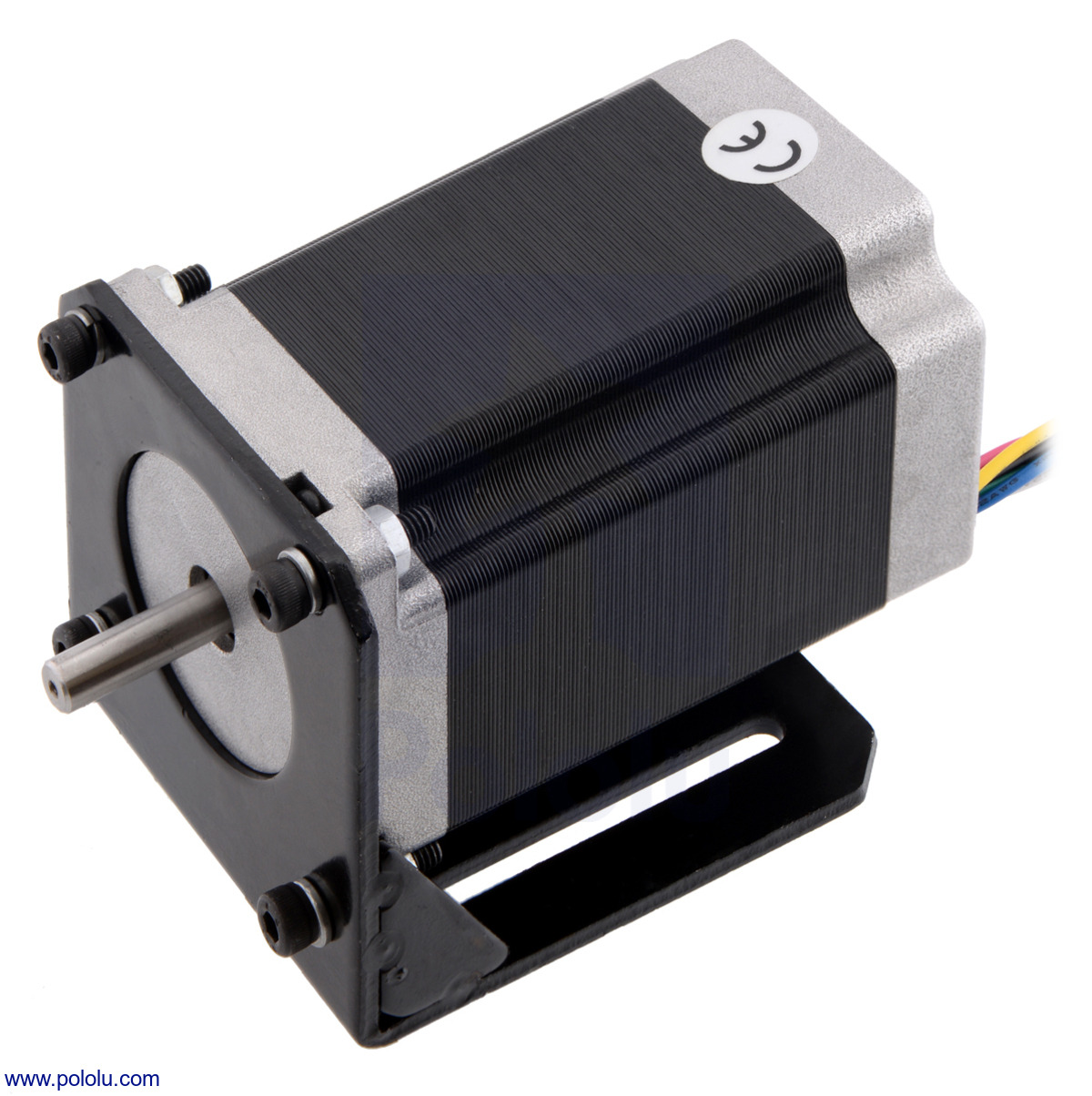 |
NEMA 23 stepper motor (item #1475) mounted with a steel L-bracket for NEMA 23 stepper motors. |
|---|
Our 1/4″ universal mounting hub and 1/4″ scooter wheel adapter can be used to mount objects on the stepper motor’s 1/4″-diameter output shaft, and we carry a NEMA 23 steel bracket for securely mounting this stepper motor to a flat surface (the picture above shows this bracket being used with a taller NEMA 23 stepper motor).
More specifications are available in the datasheet (50k pdf).
The following diagram shows the stepper motor dimensions in mm. The output shaft has a 0.25″ (6.35 mm) diameter. Though not shown in the diagram, the output is a D-shaft with a section that is flattened by 0.5 mm. This shaft works with our 1/4″ universal mounting hub and 1/4″ scooter wheel adapter.
 |
|
The inside of a bipolar stepper motor (SOYO NEMA 14-size). |
|---|
Stepper motors are generally used in a variety of applications where precise position control is desirable and the cost or complexity of a feedback control system is unwarranted. Here are a few applications where stepper motors are often found:
|
Pololu’s assortment of stepper motors. |
|---|
Note: This stepper motor is SOYO part number SY57STH41-1006A.
| Size: | 56.4 mm square × 41 mm1 |
|---|---|
| NEMA size: | 23 |
| Weight: | 450 g |
| Shaft diameter: | 6.35 mm |
| Shaft type: | 1/4 inch "D" |
|---|---|
| Current rating: | 1000 mA2 |
| Voltage rating: | 5.7 V |
| Holding torque: | 55 oz·in |
| Steps per revolution: | 200 |
| Resistance: | 5.7 Ohm2 |
| Inductance per phase: | 5.4 mH |
| Number of leads: | 6 |
| Lead length: | 30 cm |
Yes. To avoid damaging your stepper motor, you want to avoid exceeding the rated current, which is 600 mA in this instance. All of our stepper motor drivers let you limit the maximum current, so as long as you set the limit below the rated current, you will be within spec for your motor, even if the voltage exceeds the rated voltage. The voltage rating is just the voltage at which each coil draws the rated current, so the coils of your stepper motor will draw 600 mA at 3.9 V. By using a higher voltage along with active current limiting, the current is able to ramp up faster, which lets you achieve higher step rates than you could using the rated voltage.
If you do want to use a lower motor supply voltage for other reasons, consider using our DRV8834 or STSPIN-220 low-voltage stepper motor drivers.
No blog posts to show.