Arduino Uno DIP Edition

The Arduino Uno, the successor to the Arduino Duemilanove, is a microcontroller board based on a removable, dual-inline-package (DIP) ATmega328 AVR microcontroller. It has 20 digital input/output pins (of which 6 can be used as PWM outputs and 6 can be used as analog inputs), a 16 MHz resonator, a USB connection, a power jack, an in-circuit system programming (ICSP) header, and a reset button. The Arduino has an extensive support community, which makes it a very easy way to get started working with embedded electronics.
| Description | Specs (12) | Pictures (3) | Resources (12) | FAQs (0) | On the blog (2) |
|---|
Discontinuation Notice: This Arduino Uno version has been replaced by a newer revision: Arduino Uno R3.
This Arduino Uno has a removable dual-inline-package (DIP) AVR. Due to the current scarcity of this part, a functionally identical version is available that uses a surface-mount-device equivalent AVR: the Arduino Uno SMD edition. The only difference between these versions is the microcontroller package.
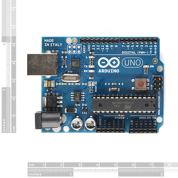 |
Arduino Uno DIP edition, top view. |
|---|
Overview
The Arduino Uno is a microcontroller board based on the ATmega328. It has 20 digital input/output pins (of which 6 can be used as PWM outputs and 6 can be used as analog inputs), a 16 MHz resonator, a USB connection, a power jack, an in-circuit system programming (ICSP) header, and a reset button. It contains everything needed to support the microcontroller; simply connect it to a computer with a USB cable or power it with a AC-to-DC adapter or battery to get started.
The Uno differs from all preceding boards in that it does not use the FTDI USB-to-serial driver chip. Instead, it features the Atmega8U2 programmed as a USB-to-serial converter. This auxiliary microcontroller has its own USB bootloader, which allows advanced users to reprogram it.
The Arduino has a large support community and an extensive set of support libraries and hardware add-on “shields” (e.g. you can easily make your Arduino wireless with our Wixel shield), making it a great introductory platform for embedded electronics. Note that we also offer a SparkFun Inventor’s Kit, which includes an Arduino Uno along with an assortment of components (e.g. breadboard, sensors, jumper wires, and LEDs) that make it possible to create a number of fun introductory projects.
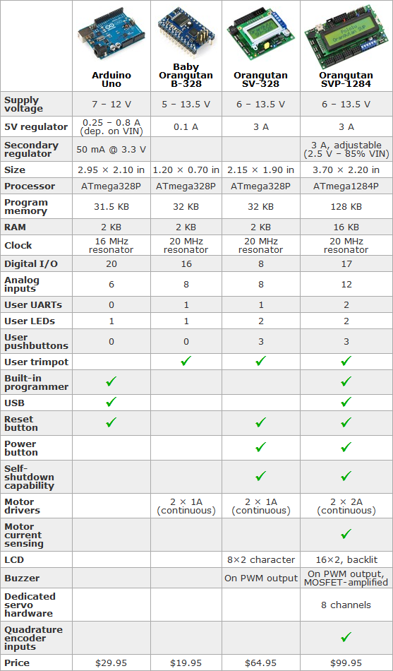 |
Comparison table for the Arduino Uno, Baby Orangutan B-328, Orangutan SV-328, and Orangutan SVP-1284. |
|---|
Summary
- Microcontroller: ATmega328
- Operating voltage: 5 V
- Input voltage (recommended): 7-12 V
- Digital I/O pins: 20 (of which 6 provide PWM output)
- Analog input pins: 6*
- DC current per I/O pin: 40 mA
- DC current for 3.3V pin: 50 mA
- Flash memory: 32 KB (ATmega328) of which 0.5 KB used by bootloader
- SRAM: 2 KB (ATmega328)
- EEPROM: 1 KB (ATmega328)
- Clock speed: 16 MHz
*The Arduino Uno has 20 total available I/O lines; all of them can function as digital I/O lines, and six of them can be used as analog inputs.
Choosing the Right Controller
The table to the right compares the Arduino Uno to Orangutan robot controllers, which are based on the same AVR architecture and feature integrated motor drivers and additional hardware suitable for robotics applications. We also offer the Basic Stamp, which offers a lot of support and educational materials for beginners, and the much higher performance mbed development board, which is based on a 96 MHz 32-bit ARM Cortex M3. See their product pages for more information.
Schematic & Reference Design
- EAGLE files: Arduino Uno reference design (207k zip)
- Schematic: Arduino Uno schematic (34k pdf)
Power
The Arduino Uno can be powered via the USB connection or with an external power supply.
External (non-USB) power can come either from an AC-to-DC adapter (wall wart) or battery. The adapter can be connected by plugging a 2.1mm center-positive plug into the board’s power jack. Leads from a battery can be inserted in the Gnd and Vin pin headers of the POWER connector.
The board can operate on an external supply of 6 to 20 volts. If supplied with less than 7 V, however, the 5V pin may supply less than five volts and the board may be unstable. If using more than 12 V, the voltage regulator may overheat and damage the board. The recommended range is 7 to 12 volts.
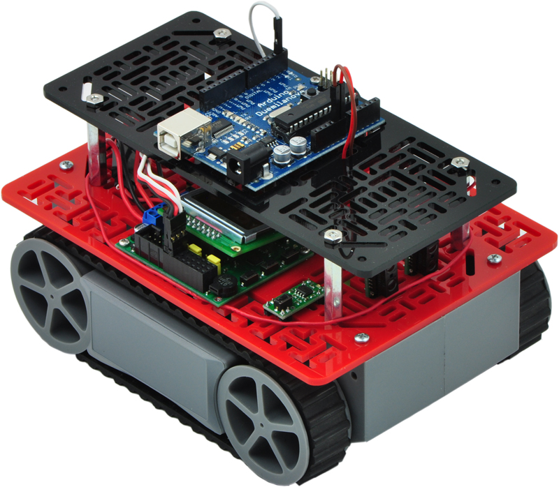 |
Two RP5/Rover 5 expansion plates with an Orangutan SV-328 and an Arduino Duemilanove. |
|---|
The power pins are as follows:
- VIN. The input voltage to the Arduino board when it’s using an external power source (as opposed to 5 volts from the USB connection or other regulated power source). You can supply voltage through this pin, or, if supplying voltage via the power jack, access it through this pin.
- 5V. The regulated power supply used to power the microcontroller and other components on the board. This can come either from VIN via an on-board regulator, or be supplied by USB or another regulated 5V supply.
- 3V3. A 3.3 volt supply generated by the on-board regulator. Maximum current draw is 50 mA.
- GND. Ground pins.
Warning: In some situations, the Arduino might allow current to flow into the USB +5V line. See this forum post for more information.
Memory
The ATmega328 has 32 KB (with 0.5 KB used for the bootloader). It also has 2 KB of SRAM and 1 KB of EEPROM (which can be read and written with the EEPROM library).
 |
Pololu 5" round robot chassis RRC04A with an Arduino Duemilanove and a QTR sensor array. |
|---|
Input and Output
Each of the 20 digital pins on the Uno can be used as an input or output, using pinMode(), digitalWrite(), and digitalRead() functions. They operate at 5 volts. Each pin can provide or receive a maximum of 40 mA and has an internal pull-up resistor (disconnected by default) of 20-50 kΩ. In addition, some pins have specialized functions:
- Serial: 0 (RX) and 1 (TX). Used to receive (RX) and transmit (TX) TTL serial data. These pins are connected to the corresponding pins of the ATmega8U2 USB-to-TTL Serial chip.
- External Interrupts: 2 and 3. These pins can be configured to trigger an interrupt on a low value, a rising or falling edge, or a change in value. See the attachInterrupt() function for details.
- PWM: 3, 5, 6, 9, 10, and 11. Provide 8-bit PWM output with the analogWrite() function.
- SPI: 10 (SS), 11 (MOSI), 12 (MISO), 13 (SCK). These pins support SPI communication using the SPI library.
- LED: 13. There is a built-in LED connected to digital pin 13. When the pin is HIGH value, the LED is on, when the pin is LOW, it’s off.
The Uno has 6 analog inputs, labeled A0 through A5, each of which provide 10 bits of resolution (i.e. 1024 different values). By default they measure from ground to 5 volts, though is it possible to change the upper end of their range using the AREF pin and the analogReference() function. Additionally, some pins have specialized functionality:
- I2C: 4 (SDA) and 5 (SCL). Support I2C (TWI) communication using the Wire library.
There are a couple of other pins on the board:
- AREF. Reference voltage for the analog inputs. Used with analogReference().
- Reset. Bring this line LOW to reset the microcontroller. Typically used to add a reset button to shields which block the one on the board.
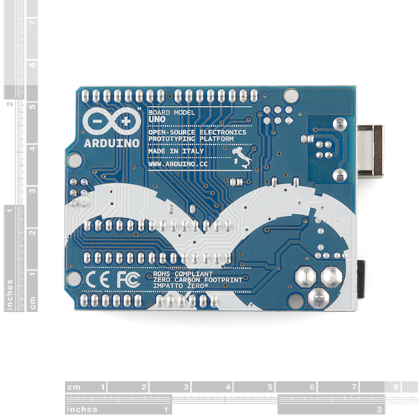 |
Arduino Uno DIP edition, bottom view. |
|---|
Communication
The Arduino Uno has a number of facilities for communicating with a computer, another Arduino, or other microcontrollers. The ATmega328 provides UART TTL (5 V) serial communication, which is available on digital pins 0 (RX) and 1 (TX). An ATmega8U2 on the board channels this serial communication over USB and appears as a virtual com port to software on the computer. The ATmega8U2 firmware uses the standard USB COM drivers, and no external driver is needed. However, on Windows, a .inf file is required. The Arduino software includes a serial monitor which allows simple textual data to be sent to and from the Arduino board. The RX and TX LEDs on the board will flash when data is being transmitted via the USB-to-serial chip and USB connection to the computer (but not for serial communication on pins 0 and 1).
A SoftwareSerial library allows for serial communication on any of the Uno’s digital pins.
The ATmega328 also supports I2C (TWI) and SPI communication. The Arduino software includes a Wire library to simplify use of the I2C bus; see the documentation for details. For SPI communication, use the SPI library.
Programming
The Arduino Uno can be programmed with the Arduino software. Select "Arduino Uno from the Tools > Board menu (according to the microcontroller on your board). For details, see the reference and tutorials.
The ATmega328 on the Arduino Uno comes preburned with a bootloader that allows you to upload new code to it without the use of an external hardware programmer. It communicates using the original STK500 protocol.
You can also bypass the bootloader and program the microcontroller through the ICSP (In-Circuit Serial Programming) header; see these instructions for details.
The ATmega8U2 firmware source code is available. The ATmega8U2 is loaded with a DFU bootloader, which can be activated by connecting the solder jumper on the back of the board (near the map of Italy) and then resetting the 8U2. You can then use Atmel’s FLIP software (Windows) or the DFU programmer (Mac OS X and Linux) to load a new firmware. Or you can use the ISP header with an external programmer (overwriting the DFU bootloader).
Automatic (Software) Reset
Rather than requiring a physical press of the reset button before an upload, the Arduino Uno is designed in a way that allows it to be reset by software running on a connected computer. One of the hardware flow control lines (DTR) of the ATmega8U2 is connected to the reset line of the ATmega328 via a 100-nanofarad capacitor. When this line is asserted (taken low), the reset line drops long enough to reset the chip. The Arduino software uses this capability to allow you to upload code by simply pressing the upload button in the Arduino environment. This means that the bootloader can have a shorter timeout, as the lowering of DTR can be well-coordinated with the start of the upload.
This setup has other implications. When the Uno is connected to either a computer running Mac OS X or Linux, it resets each time a connection is made to it from software (via USB). For the following half-second or so, the bootloader is running on the Uno. While it is programmed to ignore malformed data (i.e. anything besides an upload of new code), it will intercept the first few bytes of data sent to the board after a connection is opened. If a sketch running on the board receives one-time configuration or other data when it first starts, make sure that the software with which it communicates waits a second after opening the connection and before sending this data.
The Uno contains a trace that can be cut to disable the auto-reset. The pads on either side of the trace can be soldered together to re-enable it. It is labeled “RESET-EN”. You may also be able to disable the auto-reset by connecting a 110Ω resistor from 5V to the reset line.
USB Overcurrent Protection
The Arduino Uno has a resettable polyfuse that protects your computer’s USB ports from shorts and overcurrent. Although most computers provide their own internal protection, the fuse provides an extra layer of protection. If more than 500 mA is applied to the USB port, the fuse will automatically break the connection until the short or overload is removed.
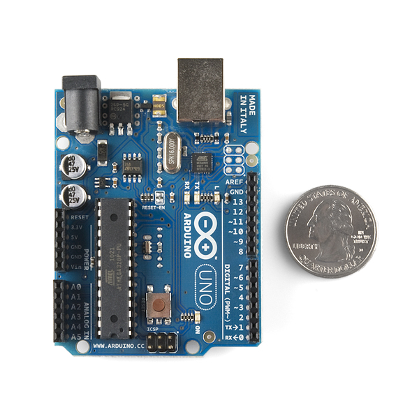 |
Arduino Uno DIP edition with U.S. quarter for size reference. |
|---|
Physical Characteristics
The maximum length and width of the Uno PCB are 2.7 and 2.1 inches respectively, with the USB connector and power jack extending beyond the former dimension. Four screw holes allow the board to be attached to a surface or case. Note that the distance between digital pins 7 and 8 is 160 mil (0.16"), not an even multiple of the 100 mil spacing of the other pins.
Note: The Arduino Uno does not include a USB cable, batteries, or a DC power adapter. No external programmer is required.
People often buy this product together with:
 |
3-Pin Female JST PH-Style Cable (30 cm) for Sharp/Socle Distance Sensors |
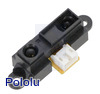 |
Sharp/Socle GP2Y0A21YK0F Analog Distance Sensor 10-80cm |
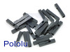 |
0.1" (2.54mm) Crimp Connector Housing: 1x1-Pin 25-Pack |
Related products


Related categories


Home | Forum | Blog | Support | Ordering Information | Wish Lists | Distributors | BIG Order Form | About | Contact
© 2001–2024 Pololu Corporation
