Support » Pololu Zumo 2040 User’s Guide » 6. The Zumo 2040 in detail »
6.9. Expansion headers and connectors
The top expansion areas on the Zumo 2040 main board (in two groups of pins near the left and right edges) break out all of the RP2040 microcontroller’s general-purpose I/O lines and provide access to various power inputs and outputs. Some of these pins are also broken out in the front expansion area, where the front sensor array connects. The following diagrams identify the locations of these pins and the hardware associated with them. These diagrams are also available as a printable PDF:
- Zumo 2040 Main Board pinout diagram (1MB pdf)
For more information about the RP2040 microcontroller and its peripherals, see the RP2040 datasheet.
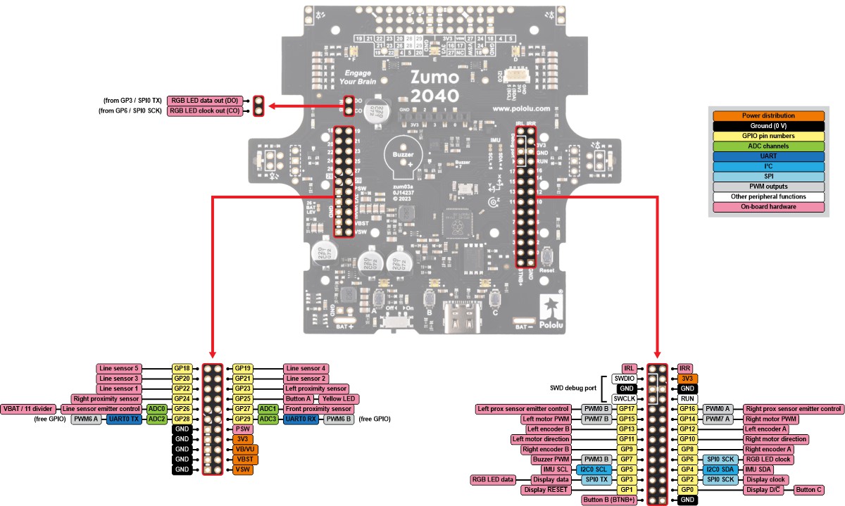 |
Zumo 2040 Main Board top expansion pinout. |
|---|
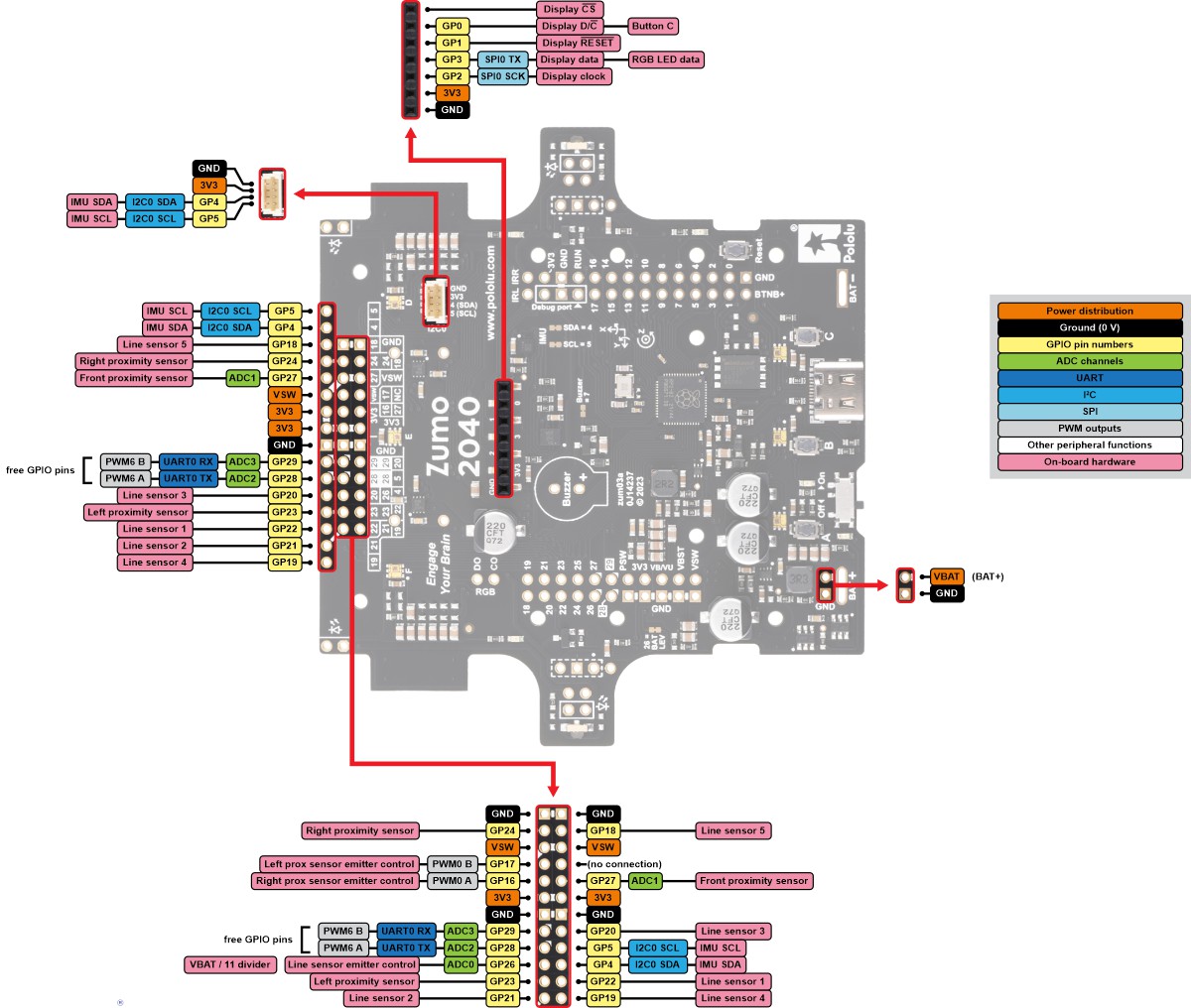 |
Zumo 2040 Main Board front expansion and display connector pinout. |
|---|
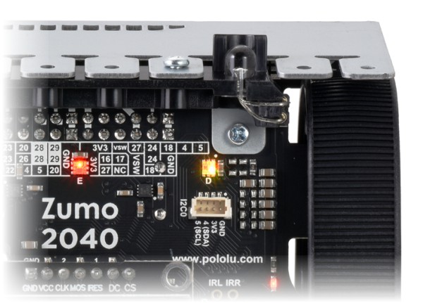
I2C0 connector
The I2C0 connector on the main board provides access to the RP2040 microcontroller’s I2C0 bus: GP4 and GP5 for SDA and SCL, respectively, along with 3V3 and GND. This 4-pin JST SH-compatible connector uses a pinout that matches that of Sparkfun’s Qwiic and Adafruit’s STEMMA QT connection systems, so it should work with most Qwiic and STEMMA QT I²C devices that accept 3.3 V.
 |


Home | Forum | Blog | Support | Ordering Information | Wish Lists | Distributors | BIG Order Form | About | Contact
© 2001–2024 Pololu Corporation
