Support » Pololu Zumo 2040 User’s Guide » 6. The Zumo 2040 in detail »
6.6. Proximity sensing
The Zumo 2040 can detect nearby objects using the three proximity sensors on the front sensor array. The proximity sensors do not emit their own light; instead they are designed to detect 56 kHz infrared (IR) signals from emitters on the Zumo 2040 Main Board.
The main board has four IR emitters:
- The middle-left and middle-right IR LEDs are surface-mounted on either side of the Zumo, inside the tracks and between the wheels. They emit light to the left and to the right.
- The front-left and front-right IR LEDs are meant to face towards the front, though you can play with the exact angle to see if it yields better results for your particular application. In the Zumo 2040 kit, these LEDs are included but must be installed by the user, as described in Section 3.
The middle-left LED and the front-left LED are in series, so you must install the front-left LED in order to use the middle-left LED, and you cannot turn on one without turning on the other. Similarly, the middle-right and front-right IR emitters are in series.
Two RP2040 pins are used to control the LEDs with PWM (pulse width modulation): GP17 controls the left proximity LEDs, and GP16 controls the right LEDs. The LEDs turn on when their corresponding control pin is high, and the brightness of the emitters can be controlled by adjusting the duty cycle of the PWM signal on the control pin. It is possible to enable the emitters on both sides at the same time, but alternating sides is usually better as it allows the Zumo to compare the readings obtained with each set of emitters.
Our example code operates the proximity sensors by transmitting pulses on the left and then the right LEDs at six different brightness levels. For each sensor, it generates two numbers: the number of brightness levels for the left LEDs that activated the sensor, and the number of brightness levels for the right LEDs that activated the sensor. A higher reading corresponds to more IR light getting reflected to the sensor, which is influenced by the size, reflectivity, proximity, and location of nearby objects. However, the presence of other sources of 56 kHz IR pulses (e.g. from another robot) can also affect the readings; even other frequencies or constant IR light can sometimes influence the sensors.
You can also just read the proximity sensors without turning on any LEDs. This could allow the Zumo to detect the IR proximity sensors of other robots, or to detect commands from a typical IR remote.
Forward LED selection
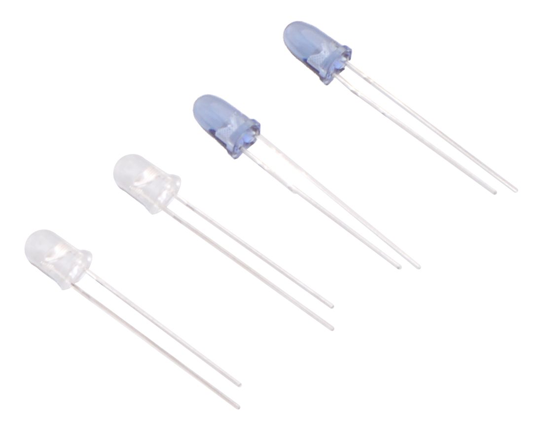 |
The kit version of the Zumo 2040 comes with two types of through-hole IR LEDs that can be installed to serve as the forward emitters. Both types of LEDs use the T-1 3/4 package, meaning they have a diameter of approximately 5 mm. Also, they both emit 940 nm light. The main difference between these LEDs is their viewing angle. The blue-colored LEDs have a relatively narrow viewing angle of 20°, which makes them better at illuminating objects far away. The clear LEDs have a much wider 50° viewing angle, which makes them better at illuminating objects that are not directly in front of the Zumo. The choice of IR LEDs to use is one way for you to customize your Zumo.
The assembled versions of the Zumo 2040 robot ship with clear (wide-angle) LEDs installed; blue (narrow-angle) LEDs are not included with these versions.
IR LED holder
Proper shielding for the forward emitters is important; without shielding, light from the LEDs can activate the proximity sensors directly and cause false readings. The Zumo 2040 comes with a plastic LED holder that serves to shield the LEDs while also holding them in place and helping to protect them from collisions with other robots. The LED holder screws to the blade with the two included 3/16″ #2-28 thread-forming screws. See the assembly instructions in Section 3 to learn how to properly install the forward emitters with the LED holder.
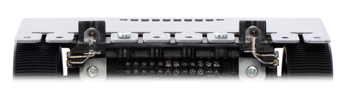 |
IR LEDs with LED holder. |
|---|
Shielding with heat shrink tubing
You can make shrouds out of black heat shrink tubing to shield the forward emitters as an alternative to using the LED holder. Without the LED holder, the LEDs are less securely mounted, but you can more easily adjust their positioning.
 |
IR LEDs with heat shrink shielding. |
|---|
You can test to see if your shielding is good by putting your Zumo on a black surface with no objects nearby and making sure that you get a reading of 0 for all the proximity sensors.
3/16″ diameter heat shrink tubing can work well, but please note that the actual diameter of heat shrink tubing often differs significantly from its nominal diameter, depending on the type and manufacturer of the tubing.
Proximity sensor performance
The proximity sensors have no particular minimum sensing distance; they can sense an object that is close to the Zumo as long as the shape of that object allows some light from the LEDs to be reflected into the sensor.
The maximum sensing distance depends on the size and reflectivity of the object you are sensing. We did several tests of the front proximity sensors to see how well they could see the steel blade of another Zumo while both robots were on the black surface of a sumo ring. In these tests, we found that the maximum sensing distance was around 30 cm to 40 cm.
There is a significant dead spot between the sensing regions of the front sensor and each side sensor. Therefore, if the Zumo senses an object with the left or right sensors and then turns to face it, there will probably be a period of time where none of the sensors can see the object.
Facing towards an object
The example Python program face_opponent.py found in the Zumo 2040 Robot Libraries and Example Code uses the motors and the proximity sensors to scan for nearby objects, face directly towards them, and track them if they move. To directly face an object, it compares two sets of readings from the sensor: the number of brightness levels for the left LEDs that resulted in the left or front sensor activating, and the number of brightness levels for the right LEDs that resulted in the right or front sensor activating. If the left reading is greater than the right reading, it means the object is closer to the left LEDs, so the robot should turn left (counter-clockwise) to face it more directly. Similarly, if the right reading is greater than the left reading, the robot should turn right (clockwise). If both of the readings are below a certain threshold, then it just turns the motors in order to scan for nearby objects.
This could be a good starting point for a sumo robot that uses the front sensors to locate its opponent.


Home | Forum | Blog | Support | Ordering Information | Lists | Distributors | BIG Order Form | About | Contact
© 2001–2026 Pololu Corporation
