Support »
Pololu Dual VNH5019 Motor Driver Shield User’s Guide
View document on multiple pages.
You can also view this document as a printable PDF.
- 1. Overview
- 2. Contacting Pololu
- 3. Getting Started with an Arduino
- 4. Using as a General-Purpose Motor Driver
- 5. Schematic Diagram
- 6. Customizing the Shield
- 7. Using the Driver in Single-Channel Mode
- 8. Current sense outputs
- 9. Differences between board revisions
1. Overview
 |
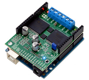
Pololu dual VNH5019 motor driver shield for Arduino. |
|---|
This user’s guide focuses on the latest version (ash02b) of the Pololu dual VNH5019 motor driver shield, but most of the information also applies to the earlier ash02a version. See Section 9 for details about the differences between board revisions.
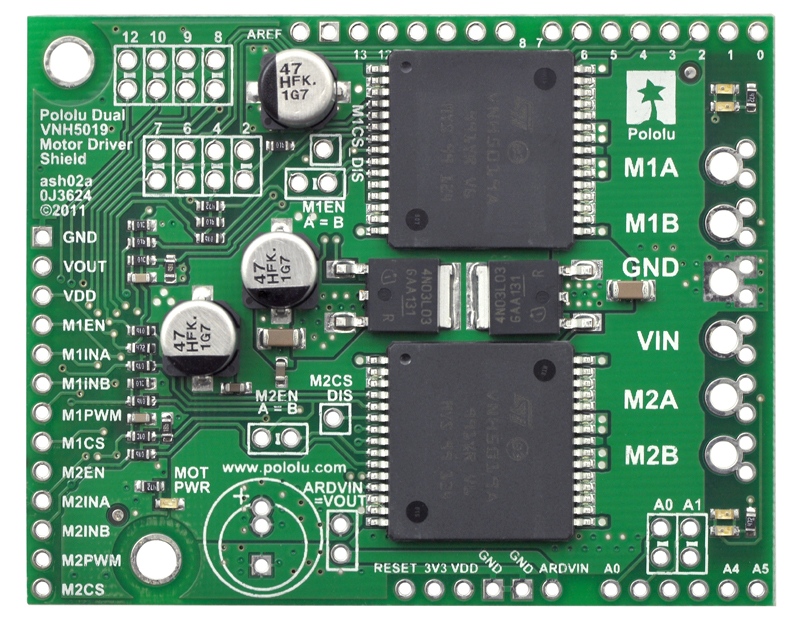
The Pololu dual VNH5019 motor driver shield for Arduino and its corresponding Arduino library make it easy to control two bidirectional, high-power DC motors with an Arduino or compatible board, such as the A-Star 32U4 Prime. The board features a pair of robust VNH5019 motor drivers from ST, which operate from 5.5 to 24 V and can deliver a continuous 12 A (30 A peak) per channel, and incorporates most of the components of the typical application diagram on page 14 of the VNH5019 datasheet (1MB pdf), including pull-up and protection resistors and FETs for reverse battery protection. It ships fully populated with its SMD components, including the two VNH5019 ICs, as shown in the picture to the right; stackable Arduino headers and terminal blocks for connecting motors and motor power are included but are not soldered in.
This versatile motor driver is intended for a wide range of users, from beginners who just want a plug-and-play motor control solution for their Arduinos (and are okay with a little soldering) to experts who want to directly interface with ST’s great motor driver ICs. The Arduino pin mappings can all be customized if the defaults are not convenient, and the VNH5019 control lines are broken out along the left side of the board, providing a convenient interface point for other microcontroller boards. This versatility, along with an option to power the Arduino directly from the shield, sets this board apart from similar competing motor shields.
1.a. Features
 |
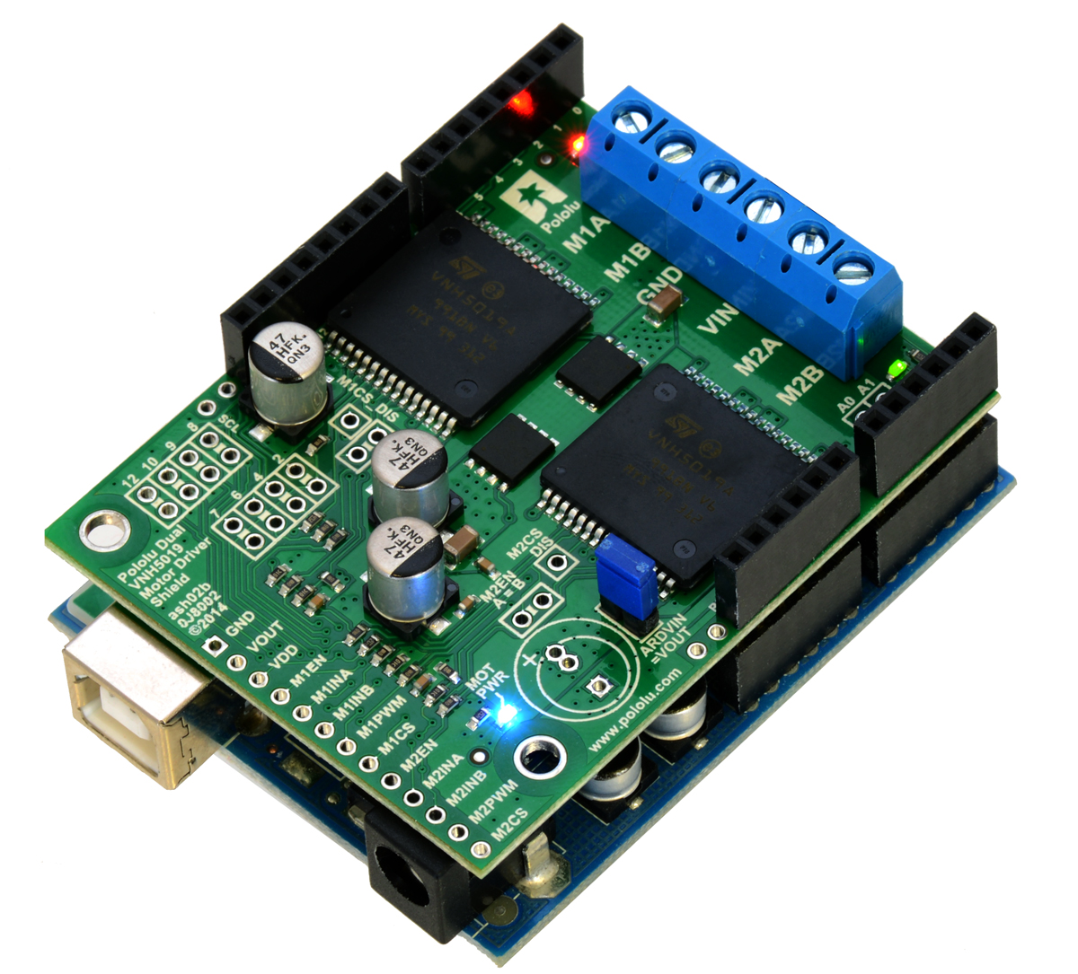
Pololu dual VNH5019 motor driver shield, assembled and connected to an Arduino Uno R3. |
|---|
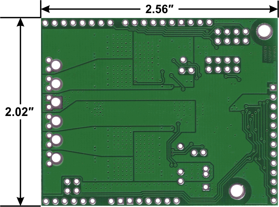 |
Pololu dual VNH5019 motor driver shield for Arduino, bottom view with board dimensions. |
|---|
- Wide operating voltage range: 5.5 – 24 V1
- High output current: up to 12 A continuous (30 maximum) per motor
- Motor outputs can be combined to deliver up to 24 A continuous (60 A maximum) to a single motor (see Section 7)
- Inputs compatible with both 5V and 3.3V systems (logic high threshold is 2.1 V)
- PWM operation up to 20 kHz, which is ultrasonic and allows for quieter motor operation
- Current sense voltage output proportional to motor current (approx. 140 mV/A)
- Motor indicator LEDs show what the outputs are doing even when no motor is connected
- Can be used with an Arduino or Arduino clone (through shield headers) or other microcontroller boards (through 0.1″ header along the left side)
- When used as a shield, the motor power supply can optionally be used to power the Arduino base as well
- Arduino pin mappings can be customized if the default mappings are not convenient
- Arduino library makes it easy to get started using this board as a motor driver shield
- Reverse-voltage protection to -16 V
- Robust drivers:
- Can survive input voltages up to 41 V
- Undervoltage and overvoltage shutdown
- High-side and low-side thermal shutdown
- Short-to-ground and short-to-Vcc protection
1 While the overvoltage protection typically activates at 27 V, it can trigger at voltages as low as 24 V, so we do not recommend using this motor driver with 24 V batteries, which significantly exceed 24 V when fully charged. If the shield is configured to power an Arduino or Arduino clone, the supply voltage must conform to that Arduino’s input voltage requirements.
1.b. Included Hardware
 |
Pololu dual VNH5019 motor driver shield for Arduino with included hardware. |
|---|
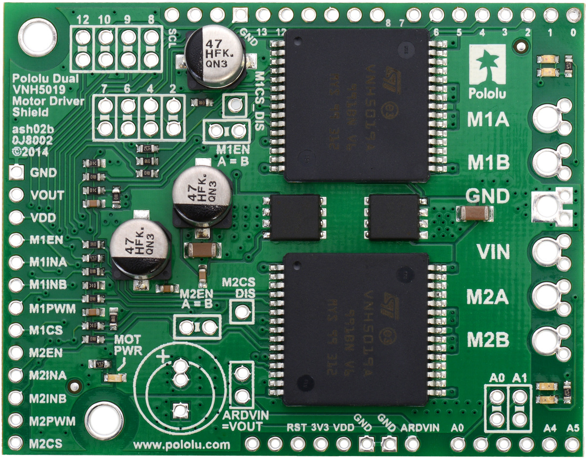
This motor driver board ships with all of the surface-mount parts populated. However, soldering is required for assembly of the included through-hole parts. The following through-hole parts are included:
- one extended/stackable 1×10 female header (for Arduino shields)
- two extended/stackable 1×8 female headers (for Arduino shields)
- two extended/stackable 1×6 female headers (for Arduino shields)
- three 2-pin, 5mm terminal blocks (for shield power and motor outputs)
- 40-pin 0.1″ straight breakaway male header (may ship in several pieces, such as two 20-pin strips)
A 0.1″ shorting block (for optionally supplying shield power to Arduino) is also included.
You can use the terminal blocks to make your motor and motor power connections, or you can break off an 12×1 section of the 0.1″ header strip and solder it into the smaller through-holes that border the six large motor and motor power pads. Note, however, that the terminal blocks are only rated for 16 A, and each header pin pair is only rated for a combined 6 A, so for higher-power applications, thick wires should be soldered directly to the board.
When not using this board as an Arduino shield, you can solder the 0.1″ headers to the logic connections along the left side of the board to enable use with custom cables or solderless breadboards, or you can solder wires directly to the board for more compact installations. Note that motor and motor power connections should not be made through a breadboard.
The motor driver includes three 47 uF electrolytic power capacitors, and there is room to add additional capacitors (e.g. to compensate for long power wires or increase stability of the power supply). Additional power capacitors are usually not necessary, and no additional capacitors are included with this motor driver.
The two mounting holes are intended for use with #4 screws (not included). They have a horizontal separation of 0.30″ and a vertical separation of 1.70″.
An Arduino is not included.
2. Contacting Pololu
|
Pololu dual VNH5019 motor driver shield, assembled and connected to an Arduino Uno R3. |
|---|
We would be delighted to hear from you about any of your projects and about your experience with the dual VNH5019 motor driver shield for Arduino. If you need technical support or have any feedback you would like to share, you can contact us directly or post on our forum. Tell us what we did well, what we could improve, what you would like to see in the future, or anything else you would like to say!
3. Getting Started with an Arduino
As with virtually all other Arduino shields, connections between the Arduino and the motor driver are made via extended stackable headers that must be soldered to the through-holes along the top and bottom edges of the shield. This section explains how to use this motor driver as an Arduino shield to quickly and easily add control of up to two DC motors to your Arduino project. For information on how to use this board as a general-purpose motor driver controlled by something other than an Arduino, see Section 4.
3.a. What You Will Need
The following tools and components are required for getting started using this motor driver as an Arduino shield:
- An Arduino or compatible control board. Using this product as an Arduino shield (rather than a general-purpose motor driver board) requires an Arduino. This shield should work with all Arduinos and Arduino clones that behave like a standard Arduino. You will also need a USB cable for connecting your Arduino to a computer. We have specifically tested this shield (using our Arduino library) with:
- A-Star 32U4 Prime
- Arduino Uno (both original and R3)
- Arduino Leonardo
- Arduino Due*
- Arduino Mega 2560
- Arduino Duemilanove (both with ATmega168 and ATmega328P)
- chipKIT Max32 Arduino-Compatible Prototyping Platform (PIC32-based Arduino clone)
- A soldering iron and solder. The through-hole parts included with the shield must be soldered in before you can plug the shield into an Arduino or before you can connect power and motors. An inexpensive soldering iron will work, but you might consider investing in a higher-performance, adjustable soldering iron if you will be doing a lot of work with electronics.
- A power supply. You will need a power supply, such as a battery pack, capable of delivering the current your motors will draw. See the Power Connections and Considerations portion of Section 3.c for more information on selecting an appropriate power supply.
- One or two brushed DC motors. This shield is a dual motor driver, so it can independently control two bidirectional brushed DC motors. See the Motor Connections and Considerations portion of Section 3.c for more information on selecting appropriate motors.
* Note for Due users: The voltage on the current sense pins will exceed the Due’s 3.3 V limit when the current draw exceeds ~23 A. The Due should generally be able to handle this since the MCU’s integrated protection diodes will clamp the input voltage to a safe value (and since the CS circuit has a 10 kΩ resistor in series with the output, only a few hundred microamps at most will flow through that diode). However, if you really want to be safe, you can use a 3.3 V zener diode to clamp the current sense output voltage to a maximum of ~3.3 V. If you want to get the full range of current feedback while using the Due, you can disconnect the shield’s current sense pins from the Due and then reconnect them through a voltage divider; see Section 6.a for more information.
3.b. Assembly for Use as an Arduino Shield
 |
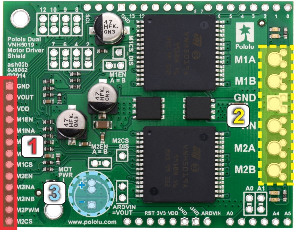
- Stackable Arduino headers: Before you can use this board as an Arduino shield, you need to solder four of the five included Arduino header strips to the set of holes highlighted in red in the picture above. The headers should be oriented so that the female sockets rest on the top side of the shield and face up while the male pins protrude down through the board, and the solder connections should be made on the underside of the shield. The newest Arduino boards, including the Uno R3 and the Leonardo, use one 10×1 header, two 8×1 headers, and one 6×1 header, as shown in the left picture below; older Arduino boards use two 8×1 headers and two 6×1 headers, as shown in the right picture below (the two pairs of pins highlighted in darker red should not be populated if you are using this board with an older Arduino that does not support these additional pins). Please make sure you solder the appropriate headers for your particular Arduino!
|
|
- Motor and power connections: The six large holes/twelve small holes on the right side of the board, highlighted in yellow in the above diagram, are the motor outputs and power inputs. You can optionally solder the included 5mm-pitch terminal blocks to the six large holes to enable temporary motor and motor power connections, or you can break off a 12×1 section of the included 0.1″ header strip and solder it into the smaller through-holes that border the six large motor and motor power pads. Note, however, that the terminal blocks are only rated for 16 A, and each header pin pair is only rated for a combined 6 A, so for higher-current applications, thick wires with high-current connectors should be soldered directly to the board. The smaller holes are intended only for 0.1″ header pins, not for the terminal blocks!
- Arduino power jumper: If you want the option of powering your Arduino and motor shield from the same source, you can solder a 2×1 piece of the included 0.1″ male header strip to the pins highlighted in orange in the above picture. Shorting across these pins with the included shorting block will connect the shield power to the Arduino’s VIN pin. You should not use this to power the shield from the Arduino as this connection is not designed to handle high currents, and you must never supply power to the Arduino’s VIN pin or power jack while this shorting block is in place, because it will create a short between the shield power supply and the Arduino power supply and will likely permanently damage something.
- Additional power capacitor: The motor driver shield includes three pre-installed 47 uF electrolytic power capacitors, and there is space—highlighted in blue in the above picture—to add an additional capacitor (e.g. to compensate for long power wires or increase stability of the power supply). An additional power capacitor is usually not necessary, and no additional capacitors are included with this shield.
The other through-holes on the shield are used for more advanced things like customizing the Arduino pin mappings and are not necessary for getting started using this shield with an Arduino. They are discussed in more detail later in this guide.
3.c. Shield Connections
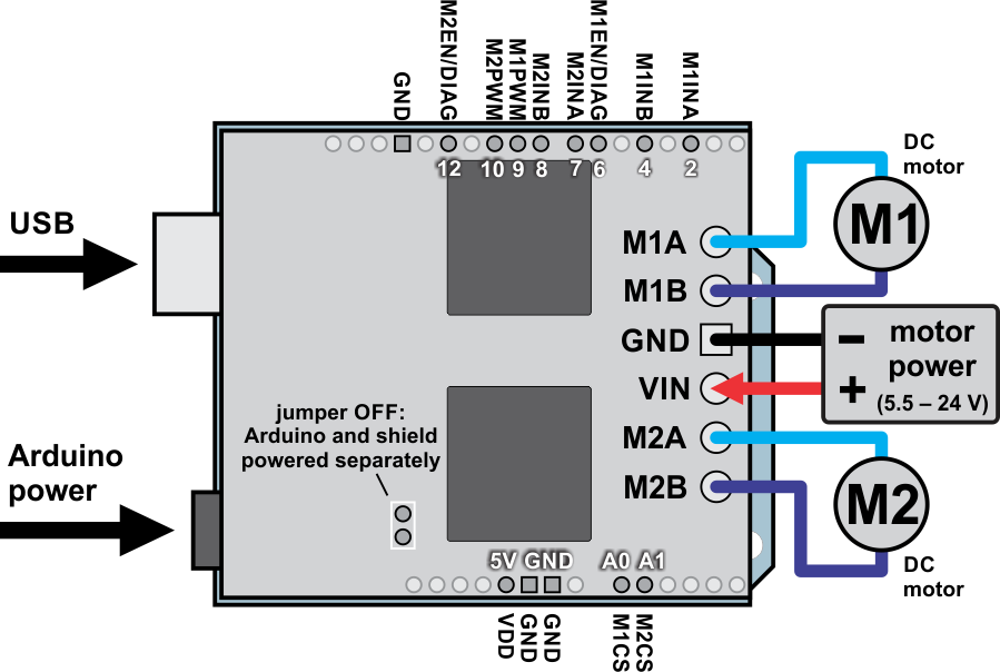 |
Dual VNH5019 motor driver shield with an Arduino (shield and Arduino powered separately). |
|---|
All of the necessary logic connections between the Arduino and the motor driver shield are made automatically when the shield is plugged into the Arduino. However, the shield’s power connections must be made directly to the shield itself via its large VIN and GND pads. The picture above shows the typical connections involved in using this board as an Arduino shield.
Default Arduino Pin Mappings
The following table shows how the shield connects your Arduino’s pins to the motor drivers’ pins:
| Arduino Pin | VNH5019 Driver Pin | Basic Function |
|---|---|---|
| Digital 2 | M1INA | Motor 1 direction input A |
| Digital 4 | M1INB | Motor 1 direction input B |
| Digital 6 | M1EN/DIAG | Motor 1 enable input/fault output |
| Digital 7 | M2INA | Motor 2 direction input A |
| Digital 8 | M2INB | Motor 2 direction input B |
| Digital 9 | M1PWM | Motor 1 speed input |
| Digital 10 | M2PWM | Motor 2 speed input |
| Digital 12 | M2EN/DIAG | Motor 2 enable input/fault output |
| Analog 0 | M1CS | Motor 1 current sense output |
| Analog 1 | M2CS | Motor 2 current sense output |
See the Pinout portion of Section 4.b for detailed descriptions of the VNH5019 driver pins and Section 5 for a schematic diagram of the shield. See Section 6.a for instructions on how to customize your board’s Arduino pin mappings if the above defaults are not convenient.
Power Connections and Considerations
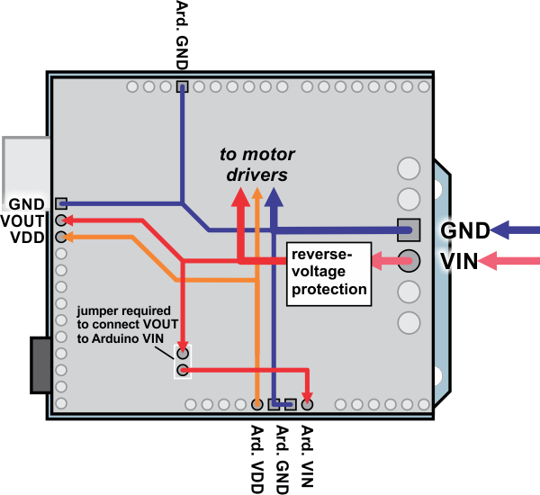 |
Dual VNH5019 motor driver shield power buses when connected to an Arduino. |
|---|
In the shield’s default state, the motor driver shield and Arduino are powered separately. When used this way, the Arduino must be powered via USB, its power jack, or its VIN pin, and the shield must be supplied with 5.5 to 24 V through the large VIN and GND pads on the right side of the board. Attempting to power the shield through other means, such as from the Arduino or through the small VOUT pin, can permanently damage both the Arduino and the shield (only the large power traces on the right side of the shield are designed to handle the high currents involved in powering motors). A high-side reverse-voltage protection MOSFET prevents the shield from being damaged if shield power is inadvertently connected backwards (for supply voltages up to 16 V; higher voltages can damage the driver if connected in reverse). Logic power, VDD, is automatically supplied by the Arduino.
Note that the motor driver features over-voltage protection that can activate at voltages as low as 24 V, so we do not recommend using it with 24 V batteries (such batteries can significantly exceed 24 V when fully charged).
It is important that you use a power source that is capable of delivering the current your motors will require. For example, alkaline cells are typically poor choices for high-current applications, and you should almost never use a 9V battery (the rectangular type with both terminals on the same side) as your motor power supply.
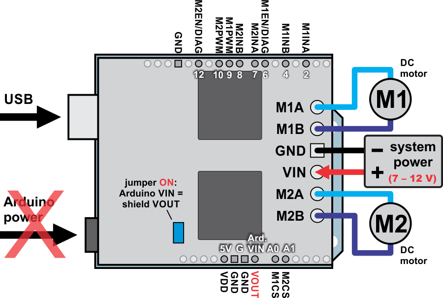 |
Dual VNH5019 motor driver shield with an Arduino (Arduino powered by the shield). |
|---|
It is also possible to power your Arduino directly from the motor shield, as shown in the diagram above, which eliminates the need for a separate Arduino power supply. When the ARDVIN=VOUT shorting block is in place, the shield’s reverse-protected input power, VOUT, is connected to the Arduino’s VIN pin. (When power is connected properly, VOUT is essentially the same as the shield’s VIN.) The Arduino’s power jack must remain disconnected at all times in this configuration.
Warning: When powering the Arduino from the motor shield, you must never connect a different power supply to the Arduino’s VIN pin or plug a power supply into the Arduino’s power jack, as doing so will create a short between the shield’s power supply and the Arduino’s power supply that could permanently damage both the Arduino and the motor shield. In this case, it is also important that your shield power supply is an acceptable voltage for your Arduino, so the full shield operating voltage range of 5.5 – 24 V probably will not be available. For example, the recommended operating voltage of the Arduino Uno is 7 – 12 V.
Note that the shorting block just routes the motor power to the Arduino VIN pin, so plugging in USB with this shorting block in place is just like plugging in USB with the Arduino powered from its power jack. On standard Arduinos we recommend against plugging a powered Arduino into USB (see this forum post for more information), but on some Arduino-compatible boards such as the A-Stars, this is completely safe.
Motor Connections and Considerations
This motor driver shield has two motor channels, M1 and M2, each of which can be used to independently control a bidirectional brushed DC motor. Each motor channel is comprised of a pair of pins—MxA and MxB—that connect to the two terminals of a DC motor and can deliver a continuous 12 A (30 A peak).
Note: It is also possible to connect a single brushed DC motor to both motor channels simultaneously to deliver nearly twice the current as is available from a channel by itself. See Section 7 for more information.
Each VNH5019 motor driver IC has a maximum continuous current rating of 30 A. However, the chips by themselves will overheat at lower currents. In our tests on a sample unit, we were able to deliver 30 A for a few milliseconds, 20 A for several seconds, 15 A for over a minute, and 12 A for around five minutes. At 6 A, the chip just barely gets noticeably warm to the touch. The actual current you can deliver will depend on how well you can keep the motor driver cool. The shield’s printed circuit board is designed to draw heat out of the motor driver chips, but performance can be improved by adding a heat sink.
This product can get hot enough to burn you long before the chip overheats. Take care when handling this product and other components connected to it.
Many motor controllers or speed controllers can have peak current ratings that are substantially higher than the continuous current rating; this is not the case with these motor drivers, which have a 30 A continuous rating and over-current protection that can activate at currents as low as 30 A (50 A typical). Therefore, the stall current of your motor should not be more than 30 A. (Even if you expect to run at a much lower average current, the motor can still draw short bursts of high currents, such as when it is starting, if special steps are not taken.)
If your motor has a stall current over the driver’s continuous current rating of 12 A per channel, we recommend you take extra steps to make sure that your motor will not be exposed to loads that will cause it to exceed 12 A for prolonged periods of time (or you take extra steps to keep the motor drivers cool, such as increasing air flow or adding heat sinks). Exceeding 12 A for long durations should not damage the shield, but it will eventually activate the driver’s thermal protection, which might result in inadequate performance for your application.
It is not unusual for the stall current of a motor to be an order of magnitude (10×) higher than its free-run current. If you do not know your motor’s stall current, you can approximate it by measuring the current it draws while held stalled at a lower voltage (such as when powered from a single battery cell) and then scaling that value linearly with voltage. For example, the stall current of a motor at 6 V is six times the stall current of that motor at 1 V. Another, less accurate method is to use a multimeter to measure the resistance between the motor terminals and then use Ohm’s law to compute the stall current I at voltage V: I = V/R. This last method generally is not as reliable because it can be difficult to measure such small resistances accurately.
Occasionally, electrical noise from a motor can interfere with the rest of the system. This can depend on a number of factors, including the power supply, system wiring, and the quality of the motor. If you notice parts of your system behaving strangely when the motor is active, first double-check that your power supply is adequate, then consider taking the following steps to decrease the impact of motor-induced electrical noise on the rest of your system:
|
||
|

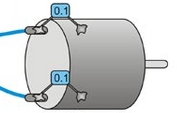
- Solder a 0.1 µF ceramic capacitor across the terminals of your motors, or solder one capacitor from each terminal to the motor case (see the pictures to the right). For the greatest noise suppression, you can use three capacitors per motor (one across the terminals and one from each terminal to the case).
- Make your motor leads as thick and as short as possible, and twist them around each other. It is also beneficial to do this with your power supply leads.
- Route your motor and power leads away from your logic connections if possible.
- Place decoupling capacitors (also known as “bypass capacitors”) across power and ground near any electronics you want to isolate from noise. These can typically range from 10 uF to a few hundred uF.
3.d. Programming Your Arduino
Our Arduino library for the dual VNH5019 motor driver shield makes it easy to get started writing your Arduino sketches. A link to download the library, installation instructions, and the library command reference can be found on the library’s github page. Once installed, we recommend you try out the example sketch by selecting
File > Examples > DualVNH5019MotorShield > Demo
from the Arduino IDE, or by copying the following code into a new sketch:
#include "DualVNH5019MotorShield.h"

DualVNH5019MotorShield md;

void stopIfFault()
{
  if (md.getM1Fault())
  {
    Serial.println("M1 fault");
    while(1);
  }
  if (md.getM2Fault())
  {
    Serial.println("M2 fault");
    while(1);
  }
}

void setup()
{
  Serial.begin(115200);
  Serial.println("Dual VNH5019 Motor Shield");
  md.init();
}

void loop()
{
  for (int i = 0; i <= 400; i++)
  {
    md.setM1Speed(i);
    stopIfFault();
    if (i%200 == 100)
    {
      Serial.print("M1 current: ");
      Serial.println(md.getM1CurrentMilliamps());
    }
    delay(2);
  }

  for (int i = 400; i >= -400; i--)
  {
    md.setM1Speed(i);
    stopIfFault();
    if (i%200 == 100)
    {
      Serial.print("M1 current: ");
      Serial.println(md.getM1CurrentMilliamps());
    }
    delay(2);
  }

  for (int i = -400; i <= 0; i++)
  {
    md.setM1Speed(i);
    stopIfFault();
    if (i%200 == 100)
    {
      Serial.print("M1 current: ");
      Serial.println(md.getM1CurrentMilliamps());
    }
    delay(2);
  }

  for (int i = 0; i <= 400; i++)
  {
    md.setM2Speed(i);
    stopIfFault();
    if (i%200 == 100)
    {
      Serial.print("M2 current: ");
      Serial.println(md.getM2CurrentMilliamps());
    }
    delay(2);
  }

  for (int i = 400; i >= -400; i--)
  {
    md.setM2Speed(i);
    stopIfFault();
    if (i%200 == 100)
    {
      Serial.print("M2 current: ");
      Serial.println(md.getM2CurrentMilliamps());
    }
    delay(2);
  }

  for (int i = -400; i <= 0; i++)
  {
    md.setM2Speed(i);
    stopIfFault();
    if (i%200 == 100)
    {
      Serial.print("M2 current: ");
      Serial.println(md.getM2CurrentMilliamps());
    }
    delay(2);
  }
}
This example ramps motor 1 speed from zero to max speed forward, to max speed reverse, and back to zero again over a period of about 3 seconds, while checking for motor faults and periodically printing the motor current to the serial monitor. It then performs the same process on motor 2 before repeating all over again.
Note: Even if you don’t have any motors yet, you can still try out this sketch and use the motor indicator LEDs for feedback that the shield is working properly.
4. Using as a General-Purpose Motor Driver
The set of pins along the left side of the shield provides direct access to the VNH5019 motor drivers, which means this board can be used as a general-purpose motor driver controlled by devices other than Arduinos. This section explains how to use the dual VNH5019 motor driver shield this way and provides some basic information about the motor driver pins to help get you started. However, we strongly encourage you to consult the VNH5019 datasheet (1MB pdf) for detailed pin descriptions, truth tables, and electrical characteristics. This shield is essentially a breakout board for two VNH5019 motor driver ICs, so the datasheet is your best resource for answering questions not covered by this user’s guide.
4.a. Assembly for Use as a General-Purpose Motor Driver
 |
- Logic connections: The 13 small holes along the left side of the board, highlighted in red in the above diagram, are used to interface with the motor drivers. You can optionally solder a 13×1 piece of the included 0.1″ male header strip to these pins. Soldering the pins so they protrude down allows the logic side of the motor driver to be plugged into a standard solderless breadboard or perfboard. You can also solder 0.1″ female headers or custom connectors to these pins.
- Motor and power connections: The six large holes/twelve small holes on the right side of the board, highlighted in yellow in the above diagram, are the motor outputs and power inputs. You can optionally solder the included 5mm-pitch terminal blocks to the board to enable temporary motor and motor power connections, or you can break off an 12×1 section of the included 0.1″ header strip and solder it into the smaller through-holes that border the six large motor and motor power pads. Note, however, that the terminal blocks are only rated for 16 A, and each header pin pair is only rated for a combined 6 A, so for higher-current applications, thick wires with high-current connectors should be soldered directly to the board.
- Additional power capacitor: The motor driver shield includes three pre-installed 47 uF electrolytic power capacitors, and there is space—highlighted in blue in the above picture—to add an additional capacitor (e.g. to compensate for long power wires or increase stability of the power supply). An additional power capacitor is usually not necessary, and no additional capacitors are included with this shield.
With the exception of the pins labeled “MxEN A=B” and “MxCS_DIS”, all of the through-holes not highlighted in the above diagram are only relevant when using this driver as an Arduino shield. The “MxEN A=B” and “MxCS_DIS” pins are explained in the “Pinout” portion of Section 4.b, but they will not be needed in typical applications and can generally be ignored.
4.b. Board Connections
 |
Dual VNH5019 motor driver shield connected to a microcontroller (gray connections are optional). |
|---|
The above diagram shows the minimum connections typically required to interface this motor driver with a microcontroller.
Pinout
The following table explains the board pins in detail. See the VNH5019 datasheet (1MB pdf) for even more detailed information about these pins, including the truth table that explains how the MxPWM and MxINA/B pins affect the MxA/B motor outputs.
| PIN | Default State | Description |
|---|---|---|
| VIN | The connection point for the positive side of the 5.5 – 24 V motor power supply. Since the overvoltage protection can be as low as 24 V, we do not recommend using 24 V batteries for VIN. | |
| VDD | The connection point for the positive side of the logic power supply (typically 2.5 – 5 V). The only function of this pin is to power the internal pull-ups on the enable lines, M1EN/DIAG and M2EN/DIAG. | |
| VOUT | This pin gives you access to the motor power supply after the reverse-voltage protection MOSFET (see the board schematic in Section 5). It can be used to supply reverse-protected power to other components in the system, but it should not be used for high currents. This pin should only be used as an output. | |
| GND | Ground connection points for logic and motor power supplies. The controlling device and the motor driver must share a common ground. | |
| MxA/B | Output of half-bridge A/B. Each half-bridge connects to one terminal of a DC motor. | |
| MxPWM | LOW | Pulse-width modulation input: a PWM signal on this pin corresponds to a PWM output on the corresponding driver’s motor outputs. When this pin is low, the motor outputs are high impedance. When it is high, the output state is determined by the states of the MxINA/B and MxEN/DIAG pins. |
| MxINA | FLOATING | Motor direction input A (“clockwise” input). |
| MxINB | FLOATING | Motor direction input B (“counterclockwise” input). |
| MxCS | Current sense output. The pin voltage is roughly 140 mV per amp of output current when the CS_DIS pin is low or disconnected. The current sense reading is more accurate at higher currents. (Note that while the CS voltage can potentially exceed 3.3 V at high currents, the current sense circuit should be safe for use with many 3.3V analog inputs. Most MCUs have integrated protection diodes that will clamp the input voltage to a safe value, and since the CS circuit has a 10 kΩ resistor in series with the output, only a few hundred microamps at most will flow through that diode.) | |
| MxEN/DIAG | HIGH | Combination enable input/diagnostic output. When the driver is functioning normally, this pin acts as an enable input, with a logical high enabling the motor outputs and a logical low disabling motor outputs. When a driver fault occurs, the IC drives this pin low and the motor outputs are disabled. Note that the VNH5019 actually has separate EN/DIAG pins for each half bridge (ENA/DIAGA and ENB/DIAGB), but these are tied together on the board by default to create a single enable input/diagnostic output for each driver. See Section 6.b for information on how to individually access ENA/DIAGA and ENB/DIAGB pins (this is typically not necessary). |
| MxCS_DIS | LOW | Disables the current sense output, MxCS, when high. Can be left disconnected in most applications. |
Power Considerations
 |
Dual VNH5019 motor driver shield power buses when not used with an Arduino shield. |
|---|
The shield must be supplied with 5.5 to 24 V through the large VIN and GND pads on the right side of the board. A high-side reverse-voltage protection MOSFET prevents the shield from being damaged if shield power is inadvertently connected backwards (for supply voltages up to 16 V; higher voltages can damage the driver if connected in reverse).
Note that the motor driver features over-voltage protection that can kick it at voltages as low as 24 V, so we do not recommend using it with 24 V batteries (such batteries can significantly exceed 24 V when fully charged).
It is important that you use a power source that is capable of delivering the current your motors will require. For example, alkaline cells are typically poor choices for high-current applications, and you should almost never use a 9V battery (the rectangular type with both terminals on the same side) as your motor power supply.
Logic power at the same level as your controlling device should be supplied to the VDD pin. This will typically be between 2.5 and 5 V, but the VNH5019 motor drivers are guaranteed to treat any logic input voltage over 2.1 V as high. The only purpose of the VDD pin is to power the pull-up resistors on the EN/DIAG lines.
Motor Considerations
The motor considerations are the same as those detailed in Section 3.c.
5. Schematic Diagram
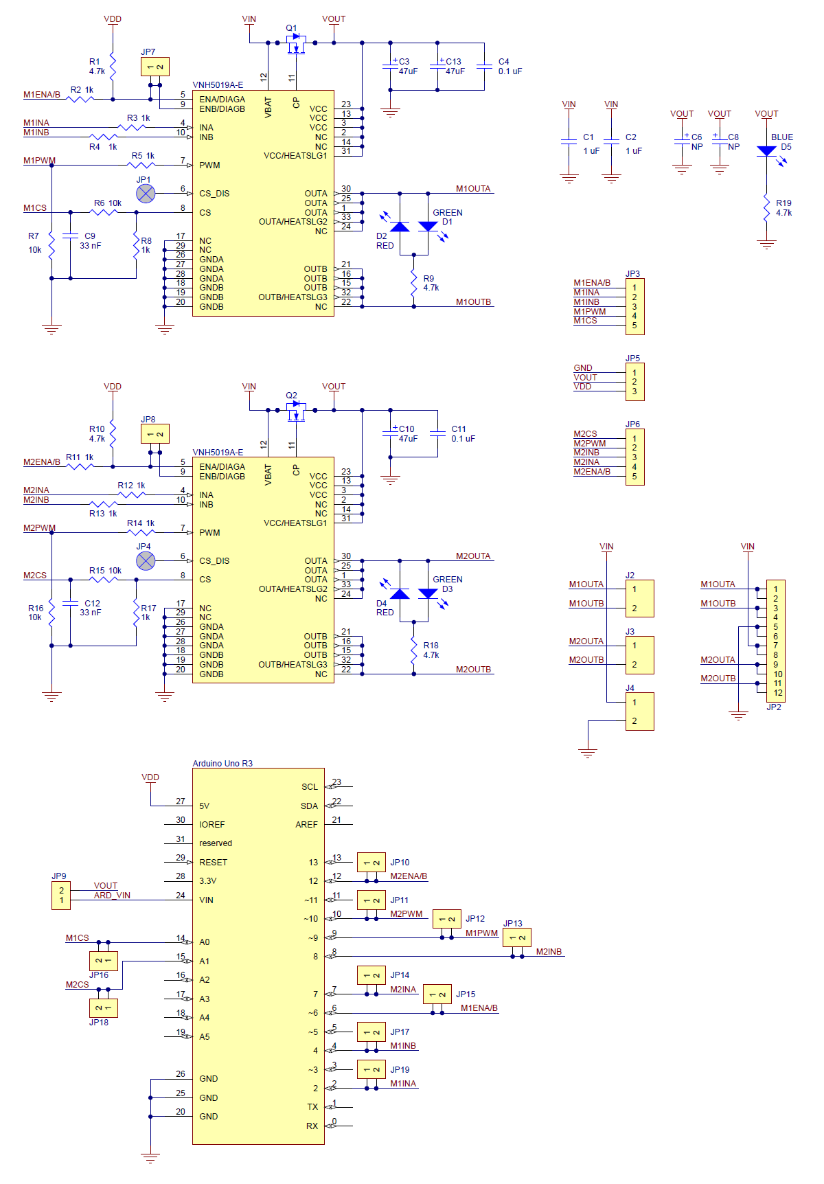 |
Schematic diagram of the Pololu dual VNH5019 motor driver shield for Arduino. |
|---|
This schematic is also available as a downloadable pdf: dual VNH5019 motor driver shield schematic (356k pdf)
This schematic is for the latest version of the shield (ash02b).
6. Customizing the Shield
This motor driver shield has several features that will not be useful in a typical application but that might benefit an advanced user. This section explains how to modify the shield from its default state to access these features.
6.a. Remapping the Arduino Connections
For some applications, this shield’s default Arduino pin mappings might not be convenient. For example, maybe you want to use the 16-bit Timer 1 for making music on a buzzer and would rather use PWMs from Timer 0 to control your motor speed. Or maybe you don’t care about monitoring the motor current and would rather use all of your analog inputs for reading sensors. With this in mind, we designed the shield to have break points in the connection between the Arduino pins and the motor drivers. It is easy to cut the connections at these points and establish new connections to replace the broken ones if desired.
The connections between the Arduino pins and the VNH5019 motor driver pins are each made through a pair of 0.1″-spaced holes that are connected on the underside of the shield by a thin trace:
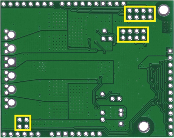 |
Cuttable traces on the dual VNH5019 motor driver shield for changing default Arduino pin mappings. |
|---|
The following two diagrams show the default pin mapping for motor drivers 1 and 2:
|
|

In all cases, the top through-hole of the pair connects to the Arduino pin and the bottom through-hole connects to the motor driver pin. To change one of the default mappings, simply use a knife to cut the trace between the appropriate pair of holes on the underside of the PCB (there is no connection to cut on the topside of the PCB) and run a wire from a different Arduino pin to the bottom hole of the pair to create a new connection. You can later use shorting blocks to restore the default pin mapping if you populate the severed hole pairs with 2×1 pieces of the included 0.1″ male header strip.
6.b. Accessing ENA/DIAGA and ENB/DIAGB Pins Separately
The VNH5019 motor drivers have separate enable/diagnostic pins for the A and B half bridges, but the shield combines these lines into a single enable/diagnostic pin for each motor driver in order to decrease the number of I/O lines required to monitor motor faults. This combined line is sufficient for most applications, but you can modify the board to get independent access to MxENA/DIAGA and MxENB/DIAGB if you want the additional information.
There are two pairs of 0.1″-spaced holes on the shield labeled “M1EN A=B” and “M2EN A=B”. These pairs are connected on the underside of the PCB by a thin trace, with the hole labeled “A” connecting to the ENA/DIAGA pin of the corresponding motor driver and the hole labeled “B” connecting to the ENB/DIAGB pin of the motor driver:
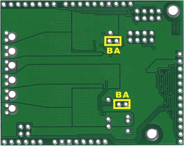 |
Cuttable traces on the dual VNH5019 motor driver shield for separately accessing ENA/DIAGA and ENB/DIAGB. |
|---|
The following diagram shows the relevant section of the board schematic:
 |
Schematic diagram of the enable/diagnostic circuit on the Pololu dual VNH5019 motor driver shield. |
|---|
To separately access both ENA/DIAGA and ENB/DIAGB, you can use a knife to cut the trace between the through-hole pair and then run a wire to the right (B) pin. Note that once the connection between the two pins is severed, only ENA/DIAGA will have the required pull-up resistor; you will need to add a separate pull-up resistor for the ENB/DIAGB pin, or connect it to a microcontroller I/O line with a built-in pull-up resistor enabled. Also, you might consider adding a 1k current-limiting resistor in series with the ENB/DIAGB connection as a safeguard against incidental shorts.
You can later use a shorting block to restore the default combined EN/DIAG line if you populate the severed hole pair with a 2×1 piece of the included 0.1″ male header strip.
7. Using the Driver in Single-Channel Mode
The dual VNH5019 motor driver shield uses two VNH5019 motor driver ICs to enable independent control of two bidirectional brushed DC motors, and each motor channel by itself is capable of delivering up to 12 A of continuous current while tolerating brief current spikes up to 30 A. If you need more power than this, however, you can combine the two motor channels into a single, doubly-powerful channel that can deliver up to a continuous 24 A (60 A peak) to one brushed DC motor. Page 23 of the VNH5019 datasheet (1MB pdf) recommends accomplishing this by using each of the two motor drivers as a half-bridge. The connections shown in the following diagram turn motor driver M1 into a new “half-bridge A” and motor driver M2 into a new “half-bridge B”:
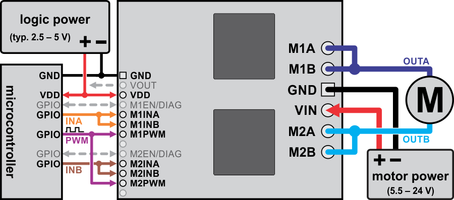 |
Using the dual VNH5019 motor driver shield to drive a single, more powerful motor. |
|---|
- Effectively create a new INA pin by connecting M1INA and MI1B to the same digital output.
- Effectively create a new INB pin by connecting M2INA and M2INB to another digital output.
- Effectively create a new PWM pin by connecting M1PWM and M2PWM to the same PWM output.
- Effectively create a new OUTA pin by connecting one motor terminal to both M1A and M1B motor outputs.
- Effectively create a new OUTB pin by connecting the other motor terminal to both M2A and M2B motor outputs.
The motor driver truth table for this new setup then becomes:
| PWM | INA | INB | OUTA | OUTB | operating mode |
|---|---|---|---|---|---|
| 0 | 0 | 0 | OPEN | OPEN | coast |
| 0 | 1 | 0 | H | OPEN | coast “clockwise”/brake “counterclockwise” |
| 0 | 0 | 1 | OPEN | H | coast "counterclockwise/brake “clockwise” |
| 0 | 1 | 1 | H | H | brake high (to VOUT) |
| 1 | 0 | 0 | L | L | brake low (to GND) |
| 1 | 1 | 0 | H | L | drive “clockwise” |
| 1 | 0 | 1 | L | H | drive “counterclockwise” |
| 1 | 1 | 1 | H | H | brake high (to VOUT) |
The above truth table assumes that both motor drivers are enabled and are not experiencing a fault condition (i.e. M1EN/DIAG and M2EN/DIAG pins are low). Otherwise, the disabled output will be “open” (high-impedance). Note that in this new configuration, the M1EN/DIAG pin effectively becomes a new ENA/DIAGA pin and the M2EN/DIAG pin effectively becomes a new ENB/DIAGB pin.
Note: In single-channel mode, the current sense feedback is disabled and the motor indicator LEDs do not illuminate.
Arduino Shield Modifications
 |
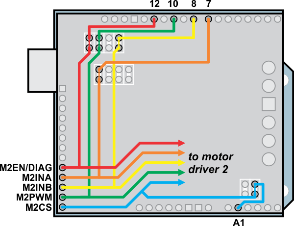
Arduino pin remapping of dual VNH5019 motor driver shield for single-channel mode (view of underside of PCB). |
|---|
If you are using this motor driver as an Arduino shield and want to reconfigure it for single-channel mode, we recommend you physically modify the Arduino pin mappings (general information on this is available in Section 6.a). While the reconfiguration could be done completely in software, doing so makes it very easy to accidentally command the motor drivers to create a short circuit that could damage something, so we advise against this approach. Instead, we recommend you do the following (in order):
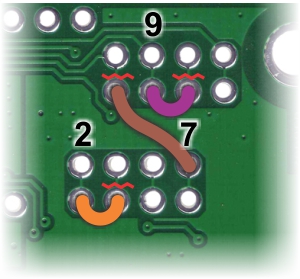
- Disconnect Arduino pins 4, 8, and 10 from driver pins M1INB, M2INB, and M2PWM, respectively, by cutting the appropriate traces on the underside of the PCB with a knife. The thin, red, wavy lines in the picture to the right show where to cut. (You can restore these connections with shorting blocks should you want to revert back to the default pin mappings later.)
- Next, connect Arduino pin 2 to M1INB, pin 7 to M2INB, and pin 9 to M2PWM. The orange, brown, and purple “wires” in the picture to the right are one example of where these connections can be made. You might find it convenient to first solder 2×1 pieces of the included 0.1″ male header strip into these holes and then use jumper wires or, in the case of neighboring pins, shorting blocks to make these connections.
To use our Arduino library with your newly reconfigured board, you should initialize your DualVNH5019MotorShield object as follows:
#include "DualVNH5019MotorShield.h"

// configure library with pins as remapped for single-channel operation
// this lets the single motor be controlled as if it were "motor 1"
DualVNH5019MotorShield md(2, 7, 9, 6, A0, 2, 7, 9, 12, A1);

void setup()
{
  md.init();
  // remaining setup code goes here
  ...
}

void loop()
{
  // loops endlessly; main loop goes here
  // the following code is a simple example:
  md.setM1Speed(400);  // single-channel motor full-speed "forward"
  delay(2000);  // wait for 2 seconds
  md.setM1Speed(0);  // single-channel motor stop (coast)
  delay(500);  // wait for 0.5 s
  md.setM1Speed(-400);  // single-channel motor full-speed "reverse"
  delay(2000);  // wait for 2 seconds
  md.setM1Speed(0);  // single-channel motor stop (coast)
  delay(500);  // wait for 0.5 s
}
When the library object is initialized this way, you can treat your single motor as if it were motor 1 (i.e. all of the “M1” library functions will work on the single motor channel). However, note that the getM1CurrentMilliamps() method will not return a meaningful result since current sense feedback is not available in single-channel mode. Also, you will need to check both M1 and M2 faults in order to get an accurate picture of the driver’s fault status: getM1Fault() effectively only returns the fault status of half-bridge A and getM2Fault() effectively returns the fault status of half-bridge B. You could conceivably connect the two fault lines together into a single fault line, but you would want to do so before the 1k protection resistors (such as by connecting them together via the “MxEN/DIAG A=B” pins, which give you access to the lines before the protection resistors).
8. Current sense outputs
The voltages on the M1CS and M2CS pins are each approximately equal to 140 mV per amp of output current for the corresponding motor. The current sense readings are more accurate at higher currents.
The current sense output pins are designed for PWM frequencies of 5 kHz or higher. If you use a PWM frequency lower than 5 kHz and want to measure the current, we recommend adding an extra capacitor between the current sense output pin and GND to smooth out the signal. For example, if you use a PWM frequency of 490 Hz and want to measure the current of M1, you should add a 1 µF capacitor (or larger) between M1CS and GND.
Note that while the M1CS and M2CS voltages can potentially exceed 3.3 V at high currents, the current sense circuit should be safe for use with many 3.3V analog inputs. Most MCUs have integrated protection diodes that will clamp the input voltage to a safe value, and since the CS circuit has a 10 kΩ resistor in series with the output, only a few hundred microamps at most will flow through that diode.
9. Differences between board revisions
There have been two versions of the dual VNH5019 motor driver shield. The revision identifier, ash02a or ash02b, can be found printed near the upper left corner of the board (below the mounting hole). While either version should generally be a drop-in replacement for the other, there are some minor differences between the two versions.
 |
The first revision, released in October 2011, was ash02a.
This version predated the Arduino Uno R3, so it lacked pass-throughs for the four new pins present on the R3 and all newer Arduinos.
Schematic diagram for revision ash02a (87k pdf)
|
The second and latest revision, released in March 2014, is ash02b.
Compared to ash02a, the following changes were made:
- Pass-throughs were added for the four additional pins (SCL, SDA, IOREF, and an unused pin) on the Arduino Uno R3 and all newer Arduinos.
- The additional capacitor through-holes, the Arduino power jumper, and the upper block of pin-remapping jumpers (for Arduino pins 8-12) were moved slightly to make room for the new pass-throughs.
- Different reverse-protection MOSFETs are used. (This does not significantly change the electrical or thermal performance of the shield.)
Schematic diagram for revision ash02b (356k pdf)


Home | Forum | Blog | Support | Ordering Information | Lists | Distributors | BIG Order Form | About | Contact
© 2001–2026 Pololu Corporation
