Support » Pololu Dual VNH5019 Motor Driver Shield User’s Guide »
7. Using the Driver in Single-Channel Mode
The dual VNH5019 motor driver shield uses two VNH5019 motor driver ICs to enable independent control of two bidirectional brushed DC motors, and each motor channel by itself is capable of delivering up to 12 A of continuous current while tolerating brief current spikes up to 30 A. If you need more power than this, however, you can combine the two motor channels into a single, doubly-powerful channel that can deliver up to a continuous 24 A (60 A peak) to one brushed DC motor. Page 23 of the VNH5019 datasheet (1MB pdf) recommends accomplishing this by using each of the two motor drivers as a half-bridge. The connections shown in the following diagram turn motor driver M1 into a new “half-bridge A” and motor driver M2 into a new “half-bridge B”:
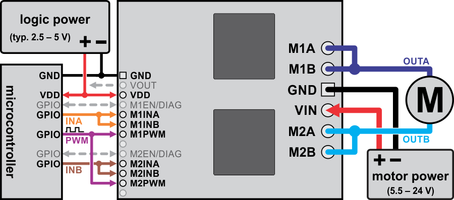 |
Using the dual VNH5019 motor driver shield to drive a single, more powerful motor. |
|---|
- Effectively create a new INA pin by connecting M1INA and M1INB to the same digital output.
- Effectively create a new INB pin by connecting M2INA and M2INB to another digital output.
- Effectively create a new PWM pin by connecting M1PWM and M2PWM to the same PWM output.
- Effectively create a new OUTA pin by connecting one motor terminal to both M1A and M1B motor outputs.
- Effectively create a new OUTB pin by connecting the other motor terminal to both M2A and M2B motor outputs.
The motor driver truth table for this new setup then becomes:
| PWM | INA | INB | OUTA | OUTB | operating mode |
|---|---|---|---|---|---|
| 0 | 0 | 0 | OPEN | OPEN | coast |
| 0 | 1 | 0 | H | OPEN | coast “clockwise”/brake “counterclockwise” |
| 0 | 0 | 1 | OPEN | H | coast "counterclockwise/brake “clockwise” |
| 0 | 1 | 1 | H | H | brake high (to VOUT) |
| 1 | 0 | 0 | L | L | brake low (to GND) |
| 1 | 1 | 0 | H | L | drive “clockwise” |
| 1 | 0 | 1 | L | H | drive “counterclockwise” |
| 1 | 1 | 1 | H | H | brake high (to VOUT) |
The above truth table assumes that both motor drivers are enabled and are not experiencing a fault condition (i.e. M1EN/DIAG and M2EN/DIAG pins are low). Otherwise, the disabled output will be “open” (high-impedance). Note that in this new configuration, the M1EN/DIAG pin effectively becomes a new ENA/DIAGA pin and the M2EN/DIAG pin effectively becomes a new ENB/DIAGB pin.
Note: In single-channel mode, the current sense feedback is disabled and the motor indicator LEDs do not illuminate.
Arduino Shield Modifications
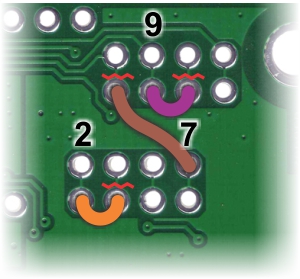 |
Arduino pin remapping of dual VNH5019 motor driver shield for single-channel mode (view of underside of PCB). |
|---|
If you are using this motor driver as an Arduino shield and want to reconfigure it for single-channel mode, we recommend you physically modify the Arduino pin mappings (general information on this is available in Section 6.a). While the reconfiguration could be done completely in software, doing so makes it very easy to accidentally command the motor drivers to create a short circuit that could damage something, so we advise against this approach. Instead, we recommend you do the following (in order):
- Disconnect Arduino pins 4, 8, and 10 from driver pins M1INB, M2INB, and M2PWM, respectively, by cutting the appropriate traces on the underside of the PCB with a knife. The thin, red, wavy lines in the picture to the right show where to cut. (You can restore these connections with shorting blocks should you want to revert back to the default pin mappings later.)
- Next, connect Arduino pin 2 to M1INB, pin 7 to M2INB, and pin 9 to M2PWM. The orange, brown, and purple “wires” in the picture to the right are one example of where these connections can be made. You might find it convenient to first solder 2×1 pieces of the included 0.1″ male header strip into these holes and then use jumper wires or, in the case of neighboring pins, shorting blocks to make these connections.
To use our Arduino library with your newly reconfigured board, you should initialize your DualVNH5019MotorShield object as follows:
#include "DualVNH5019MotorShield.h"

// configure library with pins as remapped for single-channel operation
// this lets the single motor be controlled as if it were "motor 1"
DualVNH5019MotorShield md(2, 7, 9, 6, A0, 2, 7, 9, 12, A1);

void setup()
{
  md.init();
  // remaining setup code goes here
  ...
}

void loop()
{
  // loops endlessly; main loop goes here
  // the following code is a simple example:
  md.setM1Speed(400);  // single-channel motor full-speed "forward"
  delay(2000);  // wait for 2 seconds
  md.setM1Speed(0);  // single-channel motor stop (coast)
  delay(500);  // wait for 0.5 s
  md.setM1Speed(-400);  // single-channel motor full-speed "reverse"
  delay(2000);  // wait for 2 seconds
  md.setM1Speed(0);  // single-channel motor stop (coast)
  delay(500);  // wait for 0.5 s
}
When the library object is initialized this way, you can treat your single motor as if it were motor 1 (i.e. all of the “M1” library functions will work on the single motor channel). However, note that the getM1CurrentMilliamps() method will not return a meaningful result since current sense feedback is not available in single-channel mode. Also, you will need to check both M1 and M2 faults in order to get an accurate picture of the driver’s fault status: getM1Fault() effectively only returns the fault status of half-bridge A and getM2Fault() effectively returns the fault status of half-bridge B. You could conceivably connect the two fault lines together into a single fault line, but you would want to do so before the 1k protection resistors (such as by connecting them together via the “MxEN/DIAG A=B” pins, which give you access to the lines before the protection resistors).


Home | Forum | Blog | Support | Ordering Information | Lists | Distributors | BIG Order Form | About | Contact
© 2001–2026 Pololu Corporation
