The eight red LEDs on the expansion PCB connect directly to mbed pins P13 through P20. The LEDs connect to the pins sequentially, with the outer-most LED connected to pin P13. The LEDs connect to ground through an appropriate current-limiting resistor, so they can be turned on by driving the corresponding mbed output high. If you aren’t using an mbed, you can control the LEDs by connecting I/O lines to the appropriate mbed socket pins.
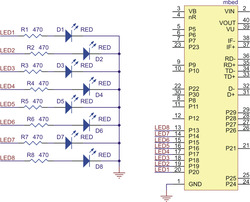 | Schematic diagram of the m3pi LEDs. |
|---|
|
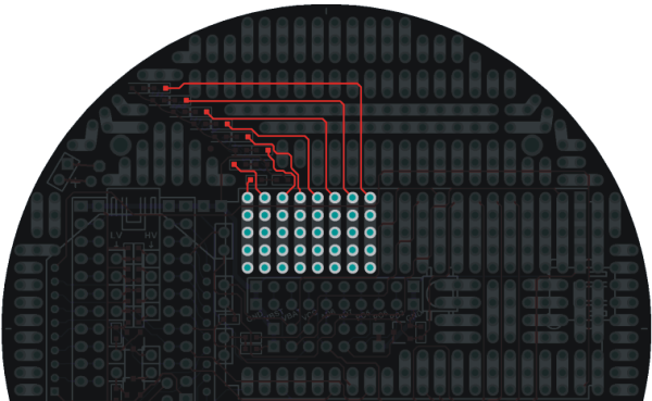
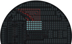 | m3pi expansion PCB LEDs. |
|---|
|
The LEDs are evenly distributed both radially and horizontally, which means they can conceivably be used for persistence of vision displays when the m3pi robot is spinning in place or driving straight. In practice, we have found that the robot does not drive fast enough in a straight line for the naked eye to perceive persistence of vision (though it could still work if you use a camera to take a picture with a long exposure time as the robot drives), but it does spin fast enough when rotating in place for the naked eye to perceive persistence of vision displays (see the pictures below).
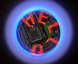 | Pololu m3pi robot writing “HELLO” with its eight mbed-controlled LEDs as it spins in place (persistence of vision). |
|---|
|
 | Pololu m3pi robot writing “HELLO” with its eight mbed-controlled LEDs as it spins in place (persistence of vision). |
|---|
|