Support » Pololu Maestro Servo Controller User’s Guide » 1. Overview »
1.b. Mini Maestro Pinout and Components
|
|
|
Note: This section applies to the Mini Maestro 12, 18, and 24 servo controllers. Please see Section 1.a for Micro Maestro pinout and component information.
The Pololu Mini Maestro 12-,18-, and 24-channel servo controllers can connect to a computer’s USB port via a USB A to mini-B cable (not included). The USB connection is used to configure the servo controller. It can also be used to send commands to the servo controller, get information about the servo controller’s current state, and send and receive TTL serial bytes on the TX and RX lines.
 |
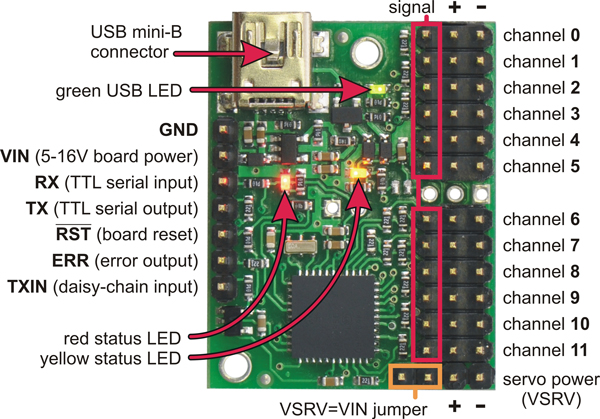
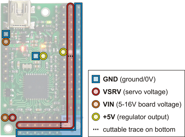
Mini Maestro 12 power pins. |
|---|
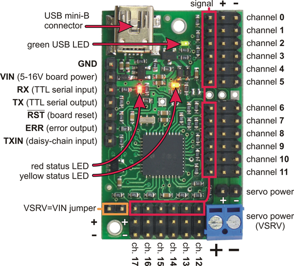
 |
Mini Maestro 18 power pins. |
|---|
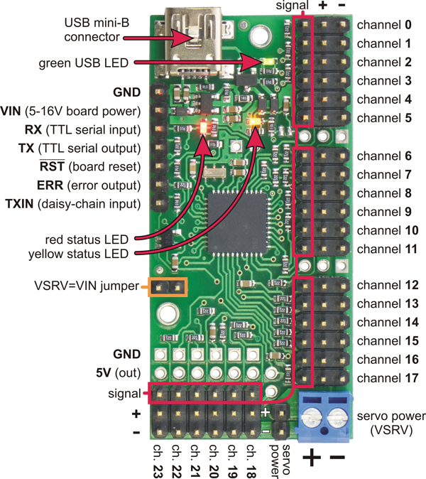
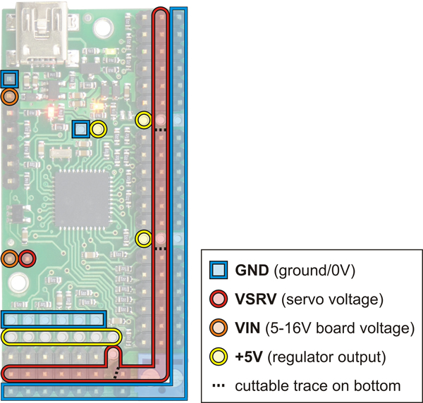 |
Mini Maestro 24 power pins. |
|---|
The processor and the servos can have separate power supplies.
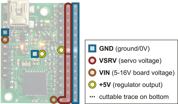
Processor power must come either from USB or from an external 5–16V power supply connected to the VIN and GND inputs on the left side of the board. It is safe to have an external power supply connected at the same time that USB is connected; in that case the processor will be powered from the external supply. Note that if the external supply falls below 5 V, correct operation is not guaranteed, even if USB is also connected.
Servo power connections are provided in the lower right corner of the Mini Maestro board. On the Mini Maestro 18 and 24, you can make servo power connections via a 2-pin terminal block or a 2-pin 0.1″ header; the Mini Maestro 12 only has a 2-pin 0.1″ header for connecting servo power. Servo power is passed directly to the servos without going through a regulator, so the only restrictions on your servo power supply are that it must be within the operating range of your servos and provide enough current for your application. Please consult the datasheets for your servos to determine an appropriate servo power source, and note that a ballpark figure for the current draw of an average straining servo is 1 A.
You can power the Maestro’s processor and servos from a single power supply by connecting the positive power line to both VIN and the servo power ports (only one ground connection is needed because all ground pins on the board are connected). The recommended way to do this is to connect your power supply to the dedicated servo power pins in the corner of the board and use the included blue shorting block to connect the pins labeled “VSRV=VIN”.
The 5V (out) power output allows you to power your own 5V devices from the 100mA on-board regulator or directly from USB. The on-board regulator is used whenever VIN is powered; in this case, since the Maestro requires 50 mA, there is about 50 mA available to power other devices.
The signal lines (0, 1, 2, …) are used for sending pulses to servos, controlling digital outputs, and measuring voltages. The total current limit (in or out) for these pins is 200 mA, but when using the on-board regulator the current out is limited to 50 mA (see above.)
The RX line is used to receive non-inverted TTL (0–5 V) serial bytes, such as those from microcontroller UARTs. These bytes can either be serial commands for the Maestro, arbitrary bytes to send back to the computer via the USB connection, or both. For more information about the Maestro’s serial interface, see Section 5.a. Note that the Maestro will probably be able to receive 3.3V TTL serial bytes, but it is not guaranteed to read 3.3V as high on the RX pin, so you should boost 3.3V TTL serial signals to above 4V if you want to ensure reliable operation.
The TX line transmits non-inverted TTL (0–5 V) serial bytes. These bytes are either generated by the Mini Maestro itself (as responses to serial commands or arbitrary bytes sent from the computer via the USB connection), or they come from the TXIN line.
The RST pin can be driven low to reset the Maestro’s microcontroller, but this should not be necessary for typical applications. The line is internally pulled high, so it is safe to leave this pin unconnected. Driving RST low is roughly equivalent to powering off the Maestro; it will not reset any of the configuration parameters stored in non-volatile memory. To reset the configuration parameters, select Device > Reset to default settings… in the Maestro Control Center.
The ERR line is an output that is tied to the red error/user LED. It is driven high when the red LED is on, and it is a pulled low through the red LED when the red LED is off. The red LED turns on when an error occurs, turns off when the error flags have been cleared, and can also be controlled by the user script. Since the ERR line is never driven low, it is safe to connect the ERR line of multiple Mini Maestros together. Please note, however, that doing this will cause the red LEDs of all connected Mini Maestros to turn on whenever one of the Mini Maestros turns on its red LED. For more information on the possible error conditions and response options, please see Section 4.e.
The TXIN line is a serial input line that makes it easy to chain together multiple Mini Maestros. Any serial bytes received on this line will be buffered through an AND gate and transmitted on the TX line. See Section 5.g for more information about daisy chaining.
 |
Bottom view with dimensions (in inches) of Pololu Micro and Mini Maestro servo controllers. |
|---|
The dimensions of the Mini Maestro PCBs are shown in the picture above, along with the Micro Maestro for comparison. The mounting holes have a diameter of 0.086″and are intended for #2 or M2 screws. The vertical and horizontal distances between the two mounting holes are as follows: 1.2″ and 0.5″ for the Mini Maestro 12, 1.58″ and 0.5″ for the Mini Maestro 18, and 1.5″ and 0.5″ for the Mini Maestro 24.
Related products


Home | Forum | Blog | Support | Ordering Information | Lists | Distributors | BIG Order Form | About | Contact
© 2001–2025 Pololu Corporation
