Support » Pololu Orangutan SVP User’s Guide » 5. Getting Started »
5.d. Assembling the kit version
This section is a guide to the connection points where you will likely want to solder hardware on to the kit version of the Orangutan SVP.
The Orangutan SVP kit version comes with these parts:
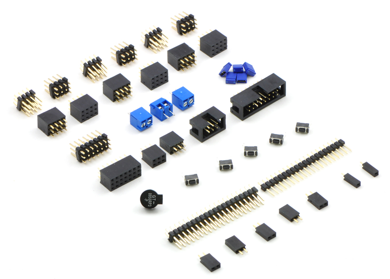 |
Hardware included with the Orangutan SVP partial kit. |
|---|
- Six 3×4 male header blocks
- Six 3×4 female header blocks
- One 3×7 male header block
- One 3×7 female header block
- Three 2-pin 3.5mm terminal blocks
- Five blue shorting blocks
- Two 2×3 female header blocks
- One 2×3 shrouded box header
- One 2×8 shrouded box header
- One buzzer
- Five pushbuttons
- One 2×20 breakaway male header
- One 1×20 breakaway male header
- Five 1×2 female header blocks
- Two single-pin female headers
The labeled photo below shows possible locations for installing these parts:
 |
Orangutan SVP kit PCB showing possible locations for included buzzer, pushbuttons, headers, and terminal blocks. |
|---|
1. Power button
To turn on your the AVR, you need to connect a power button (or a jumper at location 11). The Orangutan SVP PCB has two parallel sets of holes for the power button. You can solder a pushbutton between the wider set of holes, and/or you can make your own connection to the narrower of holes using an included 1×2 header or direct soldering. If the Orangutan is not easily accessible inside your robot, this allows you to install a momentary power switch in a more convenient location.
2. Power input
There are two parallel connection points provided for the 6–13.5V power input. You can install a 3.5mm terminal block on the large holes to accommodate large wires. You can also install a 1×2 male header on the smaller holes and plug a battery pack directly in to it.
3. Motor outputs
You can install two 3.5mm terminal blocks to accommodate your motor leads.
4. User I/O blocks
The AVR user I/O pins are divided in to four blocks. The kit comes with enough 3×4 headers so that you can choose for each block whether to make its pins female or male. You can also mix the genders together within one block using the other included headers.
5. Backlight and AREF header
If you want to be able to turn your LCD’s backlight off or use an external voltage reference source, you may want to solder a 1×2 header on to this location.
6. LCD connector
The pins in the LCD connector area are arranged so that the AVR can control an LCD using the standard 4-bit HD44780 protocol and optionally power an LCD backlight. On the assembled (non-kit) version of the Orangutan SVP, we solder a 2×8 shrouded header in to the 16 pins highlighted in the diagram. Then the 16×2 character LCD with backlight (included with the assembled version, but not the kit version) plugs in to the lower 7 rows of the connector, as well as the A and K lines on the other side of the board. If you have a different kind of LCD, consult its datasheet and the Orangutan SVP Reference Diagram (82k pdf) to determine the correct way to connect it.
7. User pushbuttons
The three user pushbuttons can be soldered in at this location.
8. Buzzer
The buzzer can be soldered in at this location.
9. Reset buttons.
A reset pushbutton can be soldered in at this location.
10. SPI/Programming connector
The assembled version comes with a 2×3 shrouded box header soldered in to this location (with the notch pointing away from the USB connector). This allows you to use an external AVR ISP programmer to program the AVR if you don’t want to use the integrated programmer for whatever reason. It also provides access to the AVR’s SPI pins, so you could use this location to connect an SPI device to your Orangutan. A 2×3 female header is provided for this location.
11. VCC-VUSB jumper
To power the board from USB, install a 1×2 male header at this location and use a blue shorting block to connect VUSB to VCC. See Section 11 for more information and caveats about using this jumper.
12. Auxiliary processor I/O block
This block contains the auxiliary processor’s A, B, C, D/RX, and TX lines, as well as several connections to GND and VCC. You can solder in either the 3×7 male or 3×7 female headers here, or mix and match genders using the other provided headers.
13. Current sense outputs
If you want access to the analog voltage output of the current-sensing circuitry for each of the motor drivers, you can solder a 1×2 female header here.
14. Servo demultiplexer block
To access the servo demultiplexer inputs, you can solder a 2×3 female or male header here.
15. Servo outputs
Most servo cables have female ends, so we recommend soldering 3×4 male headers in to the two servo output blocks. However, if you want to use the demux for something other than servos, the kits has 3×4 female headers you can use instead.
16. Servo power selection
To use your servo ports, you will need to connect a power source (no power source is connected by default). You can install two 1×3 male headers at this location and use two shorting blocks to select either VCC or VADJ for servo power.
17. LCD backlight connection and structural support
If you choose to mount a 16×2 LCD on the Orangutan SVP as is done in the assembled version, you will want to solder in the two single-pin female headers at this location. This prevents the LCD from tipping down on to the board and also powers the backlight (if your LCD has one).


Home | Forum | Blog | Support | Ordering Information | Lists | Distributors | BIG Order Form | About | Contact
© 2001–2026 Pololu Corporation
