Support » Qik 2s12v10 User’s Guide » 5. Serial Parameters and Commands »
5.a. Configuration Parameters
The qik 2s12v10 has twelve configuration parameters that are saved in non-volatile memory, which means that once set, these parameters will retain their values even if the unit is powered off. Commands 0x83 and 0x84 are used to read and write these parameter values, respectively (see Section 5.d). Please note that the memory used to store these parameters is only rated for approximately 100,000 erase/write cycles, so you should avoid putting set-parameter commands within loops that are executed many times a second; it is intended that these parameters will initially be configured as desired and then only changed occasionally. The parameters are numbered as follows:
0: Device ID
default value: 10
allowed values: 0 – 127
This parameter determines which device ID the unit responds to when the Pololu protocol is used. You should only have one qik on your serial line at a time when setting this parameter.
1: PWM Parameter
default value: 0 (high-frequency, 7-bit mode—PWM frequency of 19.7 kHz)
allowed values: 0 – 5
This parameter determines resolution and frequency of the pulse width modulation (PWM) signal used to control motor speed. Note that setting this parameter while the motors are running causes them to stop.
The least-significant bit (bit 0) selects for 7-bit resolution when cleared (i.e. a speed of 127 results in full voltage to the motors) and 8-bit resolution when set (i.e. a speed of 255 results in full voltage to the motors). A PWM with 7-bit resolution has twice the frequency of one with 8-bit resolution.
Bits 1 and 2 give you additional control over the PWM frequency. When combined with the resolution bit, PWM parameter can be set to the following six values:
- 0 = 7-bit resolution, high-frequency (PWM frequency of 19.7 kHz, which is ultrasonic)
- 1 = 8-bit resolution, high-frequency (PWM frequency of 9.8 kHz)
- 2 = 7-bit resolution, medium-frequency (PWM frequency of 2.5 kHz)
- 3 = 8-bit resolution, medium-frequency (PWM frequency of 1.2 kHz)
- 4 = 7-bit resolution, low-frequency (PWM frequency of 310 Hz)
- 5 = 8-bit resolution, low-frequency (PWM frequency of 150 Hz)
Using a PWM parameter of zero produces the highest PWM frequency of approximately 20 kHz, which is outside the range of human hearing and can help make your motors quieter. Using lower frequencies has the benefit of decreasing power losses due to switching.
2: Shut Down Motors on Error
default value: 1 (stop motors on any serial error)
allowed values: 0 – 7
This parameter controls whether motors M0 and M1 are stopped in response to the various error conditions that can occur. The three least-significant bits of the parameter let you specify whether the motors are stopped if a serial error occurs, a motor-over-current error occurs, or a motor-fault error occurs:
- bit 0: if this bit is set, stop motors M0 and M1 when any serial error occurs.
- bit 1: if this bit is set, stop motors M0 and M1 when any motor-over-current error occurs.
- bit 2: if this bit is set, stop motors M0 and M1 when any motor-fault error occurs.
When this parameter has a value of 7, both motors M0 and M1 are stopped as a safety precaution whenever any error occurs; conversely, if this parameter has a value of 0, no error causes the motors to stop. For more information on the various types of errors that can occur, see Section 5.c.
3: Serial Timeout
default value: 0 (serial timeout disabled)
allowed values: 0 – 127
When this parameter has a value of zero, the serial timeout feature is inactive. Otherwise, the value of this parameter controls how much time can elapse between receptions of valid command packets before a serial timeout error is generated. This can be used as a general safety feature to allow the qik to identify when communication with the controlling device is lost and shut down the motors as a result. Note: The shut-down-motors-on-error parameter must have bit 0—its serial error shut down bit—set for the timeout error to turn off the motors.
The timeout duration is specified in increments of 250 ms (a quarter of a second) and is calculated as the four least-significant bits (which are interpreted as a number from 0 – 15) times the quantity 2 to the three most-significant bits (which are interpreted as a number from 0 – 7) power. If the four least-significant bits are called L and the three most-significant bits are called M, the equation for the length of the timeout duration would be:
- timeout = 0.25 seconds * L * 2M = L * 2M-2 seconds
For example, if the timeout parameter is set as 0x5E (01011110 in binary), we have that L = 1110 (binary) = 14 (decimal) and M = 101 (binary) = 5 (decimal), which results in a timeout duration of:
- 0.25s * 14 * 25 = 112 seconds.
The maximum timeout duration (arising from a parameter value of 127) is 8 minutes and the minimum timeout duration (arising from a parameter value of 1) is 250 ms.
4: Motor M0 Acceleration
5: Motor M1 Acceleration
default value: 0 (controlled speed ramping disabled)
allowed values: 0 – 127
When one of these parameters has a value of zero, acceleration control of the associated motor is inactive. Otherwise, the M0 and M1 acceleration parameters control the rate at which the the M0 and M1 speeds are allowed to increase over time, respectively. These parameters provide a great way to smooth out your motor control and reduce current spikes caused by sharp increases in motor speed or changes in motor direction.
When acceleration control is active, a set-motor command tells the qik your desired target direction and speed. One of three cases can then occur:
- If the target speed is lower than the motor speed and the target direction matches the current direction, the motor speed is immediately set to the target speed.
- If the target speed is higher than the motor speed and the target direction matches the current direction, the qik linearly ramps the motor speed up to the target speed by adding the value of the associated acceleration parameter to the speed every 40 ms.
- If the target direction does not match the current direction, the motor speed is immediately set to zero, and the qik then proceeds to ramp the motor speed linearly from zero to the target speed by adding the value of the associated acceleration parameter to the speed every 40 ms.
For example, if the M0 acceleration parameter is 1, it takes a stationary motor M0 5.08 s (127 * 40 ms) to reach a speed of 127. If the M0 acceleration parameter is 127, it takes a stationary motor M0 40 ms to reach a speed of 127. The qik actually updates the motor speed 100 times per second, so the speed is really being incremented by a quarter of the acceleration parameter every 10 ms, which results in even smoother acceleration.
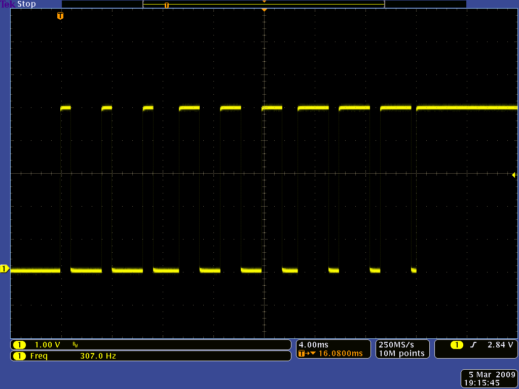
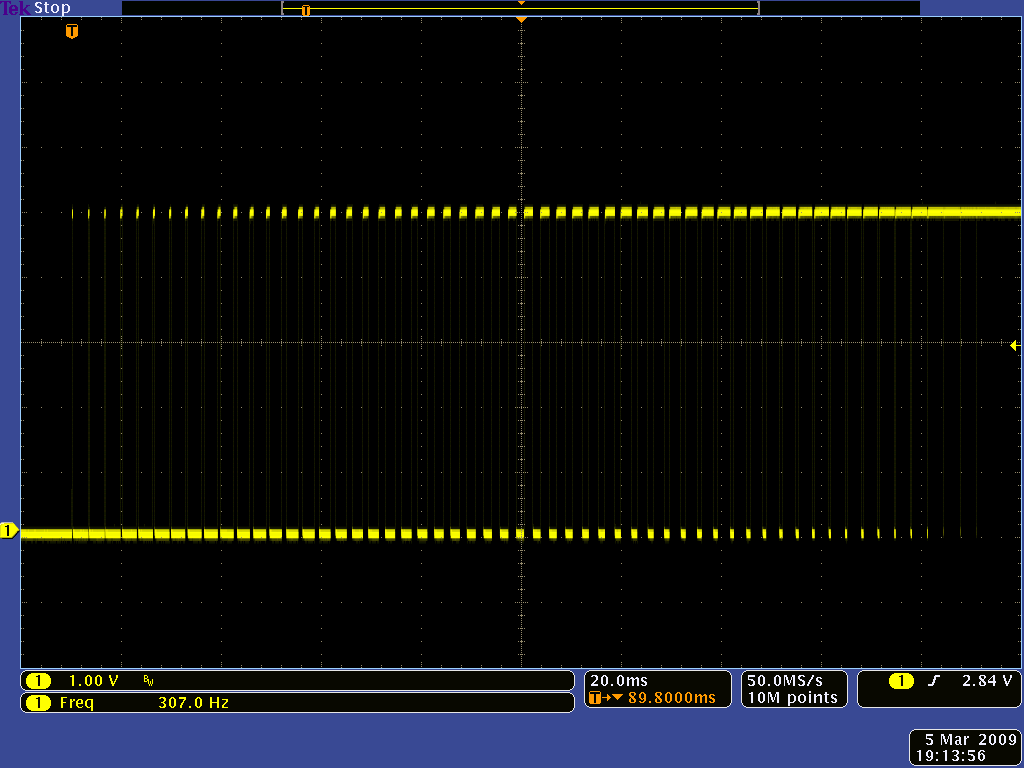
The following oscilloscope captures show qik acceleration in action. When the yellow line is low, the motor driver is in coast mode, and when the yellow line is high, the motor driver is driving with one output at VIN and the other at ground. The left capture shows the effect of using an acceleration of 127, and the right capture shows a more gradual acceleration using a parameter value of 28. The captures were taken with a low PWM frequency (310 Hz) to make it easier to see the effect of the acceleration on the motor driver output.
|
|
Please note that acceleration does not apply to braking or to a speed decrease that does not also result in a change of direction. Motor speed can also be influenced by current-limit settings, which impose additional constraints on the logic detailed above. Please see the current-limit parameters, which are documented later in this section, for more information.
6: Motor M0 Brake Duration
7: Motor M1 Brake Duration
default value: 0 (braking on direction change disabled)
allowed values: 0 – 127
When one of these parameters has a value of zero, requested changes of direction for the associated motor occur immediately. Otherwise, the M0 and M1 brake duration parameters control the amount of time motors M0 and M1 spend braking before the motor direction is changed from forward to reverse or vice versa. Along with the acceleration parameters, these parameters provide a great way to smooth out your motor control and reduce current spikes caused by changes in motor direction.
These parameters represent a time duration in units of 10 ms, so a value of 127 results in a brake duration of 1.27 s. For example, if the M0 brake duration has a value of 50 and M0 is moving forward, issuing an M0-reverse set-motor command sets motor M0 to full brake for 0.5 s before the qik acts on the set-motor command and starts moving in reverse.
8: Motor M0 Current Limit / 2
9: Motor M1 Current Limit / 2
default value: 0 (current-limiting disabled)
allowed values: 0 – 127
When one of these parameters has a value of zero, current limiting is inactive for the associated motor. Otherwise, the current-limiting behavior is determined by the current-limit response parameters (see their parameter description below for more details). Please note that these parameters specify one half of the desired current limit for each motor. For example, if you want the current limit to be 16 (which corresponds to approximately 2.4 A), you should set this parameter to 8. The current limit is compared to the an 8-bit representation of the motor current; you can request these motor currents by issuing a get-motor-current command (see Section 5.g for more information). To convert this 8-bit current representation to an approximate current, multiply it by 150 mA. To convert this parameter value to an approximate current, multiply it by 300 mA (since this parameter is multiplied by two before being compared to the motor current). Please note that the approximate current can differ from the actual current by as much as 20%.
10: Motor M0 Current-Limit Response
11: Motor M1 Current-Limit Response
default value: 4
allowed values: 0 – 127
The qik lets you limit the current motors M0 and M1 are allowed to draw. It does this by decreasing power to the motors if their currents exceed the current limits that have been set (see the description of the current-limit parameters above for more information). Specifically, every time the motor speed is updated, which happens 100 times per second, the current being drawn by the motors is compared to the current-limit parameters. The following current-limiting logic is then performed every 10 ms:
- If current limit = 0, there is no current limit; take no actions based on motor current, and use acceleration logic only, if applicable.
- Else if current-limit response = 0, generate a motor-over-current error if the motor current exceeds the current limit.
- Else add the following signed change to the motor speed, making sure the result does not exceed the target speed or go negative:
min( acceleration, response * ( current limit – current ) ) / 4
If the current-limiting feature for a motor is enabled (i.e. the current limit parameter is not zero), current limiting can affect that motor’s acceleration. The current-limit response parameters determine how the motors react when their currents are in the vicinity of their limits. If a motor’s current is just under the limit and its response parameter is small, the motor speed may not be allowed to increase as much as would be dictated by the acceleration parameter alone. If the current is over the current limit, the quantity:
- response * ( current limit – current )
becomes negative, and the effect is a reduction in motor speed. The motor speed continues to drop at a rate proportional to the difference between the current and the limit until the current equals the limit. You will most likely need to empirically determine the best response parameter for your particular application.
Related products


Home | Forum | Blog | Support | Ordering Information | Wish Lists | Distributors | BIG Order Form | About | Contact
© 2001–2024 Pololu Corporation
