Support »
PIC-Based, Obstacle-Avoiding Robot

View document on multiple pages.
You can also view this document as a printable PDF.
- 1. Introduction
- 2. Materials and Tools
- 3. Hardware Construction
- 4. Software for the PIC
- 5. Results and Conclusion
1. Introduction
 |
One of the biggest challenges in building your own robot is controlling its motors. You can find new or surplus motors and gearboxes in many places, and low-cost microcontrollers and books on how to use them abound. However, microcontrollers cannot directly drive DC motors, leaving robotics beginners with the possibly overwhelming challenge of building their own motor controller. This task is even more complicated if the motors require bidirectional operation and speed control.
This project demonstrates how easy it is to make a simple robot controller using the Pololu micro dual serial motor controller with a Microchip PIC16F628 microcontroller. We then use the circuit with the Pololu robot chassis to create a small, obstacle-avoiding robot that can serve as a starting point for more advanced projects. The low-voltage operation of the motor controller allows a small, 3.6 V cordless telephone battery pack to power the entire robot. Since the motor controller only requires two of the PIC’s 13 I/O lines, there is plenty of opportunity for expansion.
2. Materials and Tools
Here are the essential parts you will need if you want to build a similar robot. These items are available either from Pololu or from most electronic component distributors.
- Pololu micro dual serial motor controller
- Pololu robot chassis plate
- Parts to build the robot chassis, which come with our chassis combination kits:
- Tamiya twin-motor gearbox (Tamiya #70097)
- Tamiya ball caster (Tamiya #70144)
- Tamiya truck tires (Tamiya #70101)
- PIC16F627 or PIC16F628 microcontroller in a DIP (dual in-line package) from Microchip. The 16F62X microcontrollers are the only 18-pin PICs that have a built in UART (universal asynchronous receiver and transmitter), which makes transmitting data serially (to the motor controller) very simple. The code presented in this project should be portable to any other PIC with a hardware UART; with the other PICs, you would have to write your own serial routines (which isn’t that bad since you only need to transmit, and the motor controller should handle any baud rate you come up with).
- Clock source for the PIC. We used a 4 MHz ceramic resonator with built-in capacitors; any crystal, resonator, or oscillator in the 1-20 MHz range should be fine.
- 18-pin DIP socket for the PIC. You may also want a socket for your motor controller; a crude way of obtaining a 9-pin SIP (single in-line package) socket is to cut an 18-pin DIP socket in half.
- Two long-lever, snap-action switches for use as bumpers switches.
- 3.6 V, 650 mAh cordless telephone battery pack (or three AA size NiCd or NiMH batteries in a battery holder). Cordless phone batteries are available in many consmer electronics stores (e.g. Radio Shack, Best Buy) and discount stores (e.g. Wal-Mart) for around $10, making them a great power source for small robots.
- General-purpose prototyping PC board (or proto board) with space for two 18-pin DIP sockets, the ceramic resonator, and whatever other electronics you might want to fit. Such boards are available from most electronics component stores, including Radio Shack (e.g. part number 276-150A). To avoid soldering, this project could also be done using a small wireless breadboard, such as the one used in project 2.
- Hook-up wire and solder for making all of your connections.
- Double-sided foam tape provides a quick way of temporarily mounting items such as the battery pack. Alternatively, you could use standard mounting hardware or cable ties for fixing your components to the chassis.
You will probably also want to use the following:
- Pushbutton switch and 10k resistor for a reset circuit
- Two 0.1 uF capacitors to solder across the motor terminals
- Power switch
You will also need these basic tools:
- Soldering iron
- Diagonal cutters
- Wire strippers
- Scissors
- Phillips screwdriver (for building the gearbox and ball caster)
- Hot glue gun (optional)
3. Hardware Construction
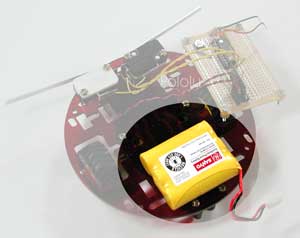 |
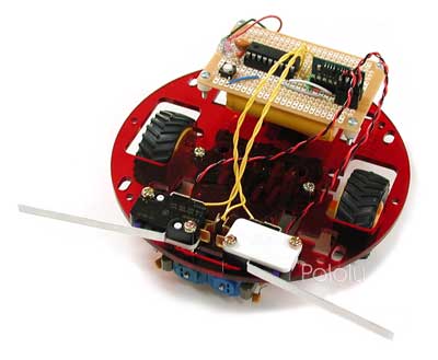
Begin by assembling the robot chassis. You should mount the battery pack on the rear of the robot, above the ball caster, to balance the weight of the motors. Double-sided foam tape is a convenient method of attaching the battery pack; it can also be secured with cable-ties by using the rectangular holes on both sides of the ball caster. If you are using a battery holder, you can easily drill mounting holes through the holder or the chassis if existing holes do not line up.
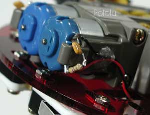 |
When soldering to the motor leads, be careful not to damage them. Soldering a small capacitor across the motor leads can improve the performance of the motor controller and lower interference with other electronics on your robot. We used a 0.1 uF ceramic capactitor.
The picture to the right shows a resistor in series with the capacitor. In general, such a resistor limits the current wasted by the PWM (pulse width modulation) in charging and discharging the capacitor. However, the relatively low, 600 Hz PWM frequency of the motor controller makes this resistor unnecessary; we saw no added benefit when we added the resistor.
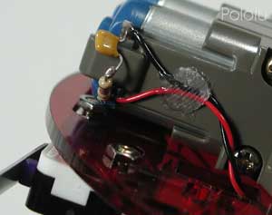 |
Because the motor leads are fragile, it is important to provide strain relief for the wires you connect to the motor. For our example, we hot-glued the leads to the side of the gearbox, as shown in the picture. Securing the wires this way will allow you to manipulate the other end of the wires without worrying about breaking off the motor leads. Note that the glued wires prevent removal of the motors from the gearbox. Hot glue has the advantage of not being entirely permanent; if necessary, it’s not too difficult to free the wires.
We have kept the motor capacitor exposed for the purposes of these pictures, but it’s a good idea to protect them as much as possible, especially since they are low to the ground and on the front end of the robot.
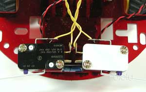 |
To keep this project as simple as possible, we limit our sensors to two snap-action swtiches for front collision detection. Of course, you can add more sophisticated sensors for more interesting behavior.
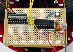 |
As you can see in the picture to the right, there isn’t much to the electronics. We soldered the circuit on a small perforated board, but you can also use a solderless breadboard. The small pushbutton switch on the top right and the resistor below it make up an optional reset circuit. The only other components are the PIC, the resonator (lower right), and the motor controller. No additional resistors are required for the bump switches because we use the PIC’s internal pull-up resistors on port B.
 |
The main reason for using the PIC16F628 is that it has a hardware UART; to make use of it, we must connect the TX pin, pin RB2, to the motor controller’s serial input. Connecting the motor controller reset pin is optional, but using it prevents any baud rate detection problems during power-up. If you don’t have any extra I/O lines, you can connect the reset input to the PIC reset circuit.
Note that the bumper switches must be connected to port B pins in order to make use of the PIC’s internal pull-up resistors. Nine of the PIC I/O lines are unused and available for expansion. As you add additional electronics, you may need to add 0.1 uF bypass capacitors from power to ground to keep the power supply clean.
As you can see in the picture to the right, there isn’t much to the electronics. We soldered the circuit on a small perforated board, but you can also use a solderless breadboard. The small pushbutton switch on the top right and the resistor below it make up an optional reset circuit. The only other components are the PIC, the resonator (lower right), and the motor controller. No additional resistors are required for the bump switches because we use the PIC’s internal pull-up resistors on port B.
4. Software for the PIC
Using the motor controller is very simple, even if you program your PIC in assembly. This sample program makes our little robot drive forward until it hits an obstacle; once it does, it backs up, turns away from the side where the collision occured, and resumes moving forward. All of the code below uses the standard assembly language supported by Microchip’s MPLAB development software. Even if you are using a different assembler or compiler, this example should give you a good start.
First, we name the registers and bits that we will use throughout the rest of the program:
;****** Equates ****************************************************************

Bank0RAM	equ	020h	;start of bank 0 RAM area

SMC_PORT	equ	PORTB	;motor controller on port b
BMP_PORT	equ	PORTB	;bumper switches on port b

;bit equates
SOUT		equ	2	;serial output to motor controller
SRST		equ	3	;to reset pin on motor controller
LBMP		equ	4	;left bumper switch
RBMP		equ	5	;right bumper switch

;****** Variables **************************************************************

	cblock	Bank0RAM
	ARG1L
	ARG1H
	BYTE3	;for storing bytes 3 and 4 in the serial protocol
	BYTE4
	endc
It’s also convenient to have a subroutine for making precise pauses. This routine takes the 16-bit value in ARG1H and ARG1L and delays for approximately that many milliseconds. Of course, the length of the delay is dependent on the clock speed, which is 4 MHz in our example.
milliDelay
	movlw	.250		;outer loop
	addlw	0xFF		;inner loop
	btfss	STATUS,Z
	goto	$-2		;goto inner loop

	movlw	1		;16-bit decrement
	subwf	ARG1L,f
	btfss	STATUS,C
	decf	ARG1H,f

	movf	ARG1H,f		;16-bit test if zero
	btfsc	STATUS,Z
	movf	ARG1L,f
	btfsc	STATUS,Z
	return
	goto	milliDelay
We are now ready to approach the main program, which begins by configuring the UART and resetting the motor controller. The 2 millisecond pause at the end gives the motor controller some time between resetting and receiving serial input.
	org	0x05
startMain
	;set up I/O ports and serial port for 19,200 baud UART
	bsf	STATUS,RP0
	movlw	b'11110111'	;smc reset is the only normal
	movwf	TRISB		; output--all others inputs or serial out
	bcf	OPTION_REG,NOT_RBPU	;enable PORTB pull-up resistors
	movlw	.12		;set baud rate to 19,200 (assuming BRGH=1)
	movwf	SPBRG		;(address 99h)
	movlw	b'00100100'	;bit 6 clear - 8-bit transmission
				;bit 5 set - enable transmit
				;bit 4 clear - UART asynchronous mode
				;bit 2 set - high baud rate mode
				;bits 7, 3, 1, 0 - don't care
	movwf	TXSTA		;address 98h
	bcf	STATUS,RP0	;select bank 0
	movlw	b'10010000'	;bit 7 set - enable serial port
				;bit 6 clear - 8-bit reception
				;bit 4 set - continuous receive
				;bits 5, 3:0 - don't care
	movwf	RCSTA		;address 18h
	;reset motor controller
	bcf	SMC_PORT,SRST
	nop
	nop
	bsf	SMC_PORT,SRST
	movlw	0x00
	movwf	ARG1H
	movlw	0x02
	movwf	ARG1L
	call	milliDelay
The program is now ready to run its main loop, in which it
checks the bumper switches and takes the appropriate action.
Two supporting subroutines, updateMotor and pause, are
shown later; updateMotor sends a 4-byte command to the
motor controller based on BYTE3 and BYTE4, and pause stops
both motors for 50 ms. pause is used to keep the motors
from having to instantly switch from forward to reverse,
which causes a current surge that can exceed the
motor controller’s maximum current specification of 1 A.
mainLoop
	btfss	BMP_PORT,LBMP
	goto	left_bump
	btfss	BMP_PORT,RBMP
	goto	right_bump
	;no bumps, so just go straight
	movlw	0x00		;right motor, forward
	movwf	BYTE3
	movlw	0x7F		;full speed
	movwf	BYTE4
	call	updateMotor
	movlw	0x02		;right motor, forward
	movwf	BYTE3
	movlw	0x7F		;full speed
	movwf	BYTE4
	call	updateMotor
	goto	mainLoop

left_bump
	call	pause
	movlw	0x03		;right motor, backward
	movwf	BYTE3
	movlw	0x7F		;full speed
	movwf	BYTE4
	call	updateMotor
	movlw	0x01		;left motor, backward
	movwf	BYTE3
	movlw	0x3F		;half speed
	movwf	BYTE4
	call	updateMotor
	movlw	HIGH .1500	;pause 1.5 seconds (1500 ms)
	movwf	ARG1H
	movlw	LOW .1500
	movwf	ARG1L
	call	milliDelay
	call	pause
	goto	mainLoop

right_bump
	call	pause
	movlw	0x03		;right motor, backward
	movwf	BYTE3
	movlw	0x3F		;half speed
	movwf	BYTE4
	call	updateMotor
	movlw	0x01		;left motor, backward
	movwf	BYTE3
	movlw	0x7F		;full speed
	movwf	BYTE4
	call	updateMotor
	movlw	HIGH .1500	;pause 1.5 seconds (1500 ms)
	movwf	ARG1H
	movlw	LOW .1500
	movwf	ARG1L
	call	milliDelay
	call	pause
	goto	mainLoop
Finally, here are the subroutines called from the main loop. The updateMotor
subroutine sends the motor controller the 4-byte control sequence of 0x80 and 0x00
followed by the motor number and direction, specified in BYTE3, and the
speed, specified in BYTE4. To keep this example program simple,
this subroutine does not exit until all four
bytes have been copied to the transmit buffer. The program could be
made more efficient by using interrupts, allowing the PIC to perform
other tasks while the UART is busy transmitting.
updateMotor
	btfss	PIR1,TXIF
	goto	updateMotor
	movlw	0x80
	movwf	TXREG
	nop
updateMotor2
	btfss	PIR1,TXIF
	goto	updateMotor2
	movlw	0x00
	movwf	TXREG
	nop
updateMotor3
	btfss	PIR1,TXIF
	goto	updateMotor3
	movf	BYTE3,W
	movwf	TXREG
	nop
updateMotor4
	btfss	PIR1,TXIF
	goto	updateMotor4
	movf	BYTE4,W
	movwf	TXREG
	return

pause
	movlw	0x02		;right motor off
	movwf	BYTE3
	movlw	0x00
	movwf	BYTE4
	call	updateMotor
	movlw	0x00		;left motor off
	movwf	BYTE3
	movlw	0x00
	movwf	BYTE4
	call	updateMotor
	movlw	HIGH .50	;pause 0.05 second (50 ms)
	movwf	ARG1H
	movlw	LOW .50
	movwf	ARG1L
	call	milliDelay
	return
| Note: Make sure the watchdog timer is disabled in the configuration bits. The brown-out detection feature must also be turned off for the PIC to operate off of the 3.6 V power source. |
5. Results and Conclusion
Our robot performed as expected, and it was fairly entertaining to watch it bounce around the room. The bumper switches are far from perfect, with a blind area in the center of the robot that can get the robot stuck behind table legs and other obstacles too narrow to trigger either of the switches. This problem could be avoided by adding a third, center switch, or by making the robot turn randomly every once in a while.
One serious problem we did initially encounter was with changing the direction of the motors from full speed in one direction to full speed in the other direction. In highly cluttered areas, in which the robot frequently hit obstacles and changed directions, the motor controller would sometimes heat up to the point where the thermal cutoff kicked in, causing the robot to stop for approximately one second. After adding the 50 ms pauses between switching directions, we did not have any problems with the motor controller overheating.
This project shows that building a small robot is very simple when using the Pololu motor controller. In only a few hours, we built a functioning robot that can serve as a starting point for more complicated robots. If you are ready to tackle a new project, you might try adding on our IR beacon to allow the robot to run away from another robot.


Home | Forum | Blog | Support | Ordering Information | Wish Lists | Distributors | BIG Order Form | About | Contact
© 2001–2024 Pololu Corporation
