Addressable RGB 150-LED Strip, 5V, 5m, (Low-Speed TM1804)

This 5-meter long strip contains 150 RGB LEDs that can be individually addressed using a one-wire interface, allowing you full control over the color of each RGB LED. The waterproof, adhesive-backed strip runs on 5 V and can be chained with additional low-speed TM1804 strips to form longer runs or cut apart between each LED for shorter segments.
Alternatives available with variations in these parameter(s): length Select variant…
| Description | Specs (6) | Pictures (14) | Resources (3) | FAQs (2) | On the blog (0) | Distributors (0) |
|---|
Discontinuation notice: These LED strips have been replaced by newer versions that allow for approximately twice the update rate. The new versions are similarly available in 1m, 2m and 5m lengths and have a similar control interface, but timing differences mean the old and new versions are not compatible with each other and cannot be combined in the same chain.
Overview
These RGB LED strips are an easy way to add complex lighting effects to a project. A dedicated driver IC for each LED allows you to control the color and brightness of each LED independently. The strips are available in lengths of 1 meter (30 LEDs), 2 meters (60 LEDs), and 5 meters (150 LEDs).
 |
 |
 |
 |
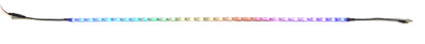
Weatherproof coating and 3M adhesive backing on an addressable RGB LED strip. |
|---|
Features
- Individually addressable RGB LEDs (30 LEDs per meter)
- 24-bit color control (8-bit PWM per channel); 16.8 million colors per pixel
- One-wire communication interface
- 5 V operating voltage
- 12 mm width, 2.6 mm thickness
- Waterproof
- 3M adhesive backing
- Pre-terminated with power and data connectors on both ends
Using the LED strip
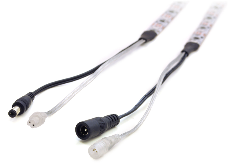 |
Connectors on an addressable RGB LED strip. |
|---|
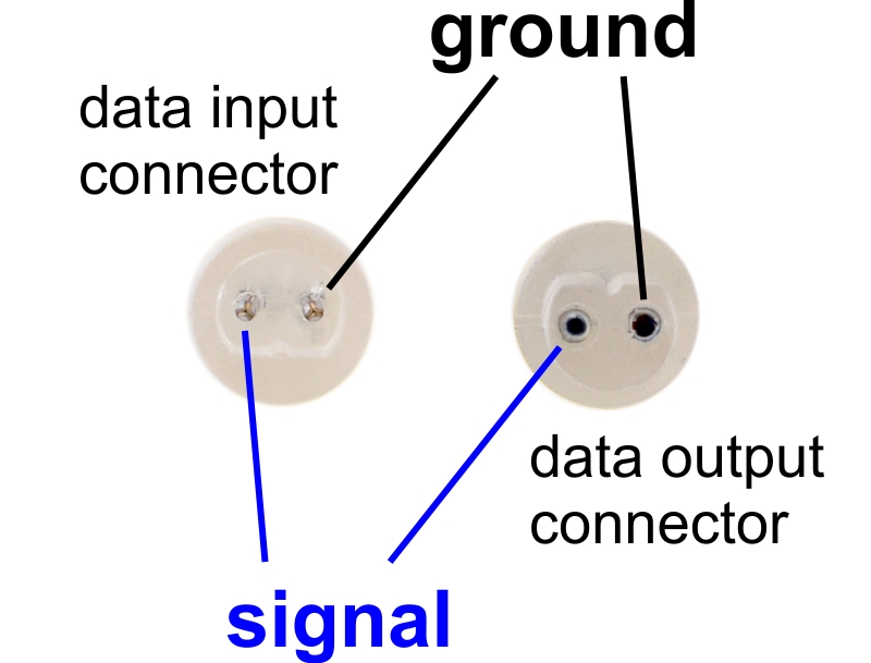 |
Labeled data connector diagram for the addressable RGB LED strips. |
|---|
Each LED strip has four connectors (except for the 5 m strip, which does not have a power output). These can be seen in the adjacent picture, from right to left: data input and power input on one end of the strip, data output and power output on the other end. The data and power output connectors are only used when chaining multiple strips together.
- The data input connector for the LED strip is transparent and has two male pins inside, separated by about 0.1″. When looking into the connector and orienting it with the flattened side on the bottom, the left pin is the signal wire and the right pin is ground. To control the LED strip from a microcontroller, the LED strip’s ground should be connected to ground on the microcontroller, and the LED strip’s signal line should be connected to one of the microcontroller’s I/O lines. The male pins inside the connector fit the female terminations on our premium jumper wires and wires with pre-crimped terminals.
- The power input connector is a center-positive barrel jack with a 2.1 mm diameter pole. Our 5 V wall power adapters plug into this jack and work well for powering these LED strips. With all the LEDs on full brightness, the 1 m strip draws approximately 1.5 A, the 2 m strip draws approximately 2.4 A, and the 5 m strip draws approximately 4 A, so be sure to select a power source that can handle the strip’s current requirements.
- The data output connector is transparent and has two female receptacles inside, separated by about 0.1″.
- The power output connector is a center-positive 5.5 × 2.1 mm barrel connector. The 5 m strip does not have this connector.
The ground wires on all four connectors are electrically connected.
Note: The white stripe visible on one of the data connector wires is not a good indicator of polarity. Please use the labeled connector diagram to help determine which pin is the signal pin and which is ground. You can also verify the ground pin with a multimeter by checking for continuity between the pin and the outer ring of the power connector.
Chaining
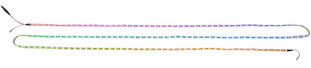
Multiple LED strips can be chained together by connecting the input connectors from one strip to the output connectors from another strip. When the data connectors on several strips are chained this way, they can be controlled as one continuous strip.
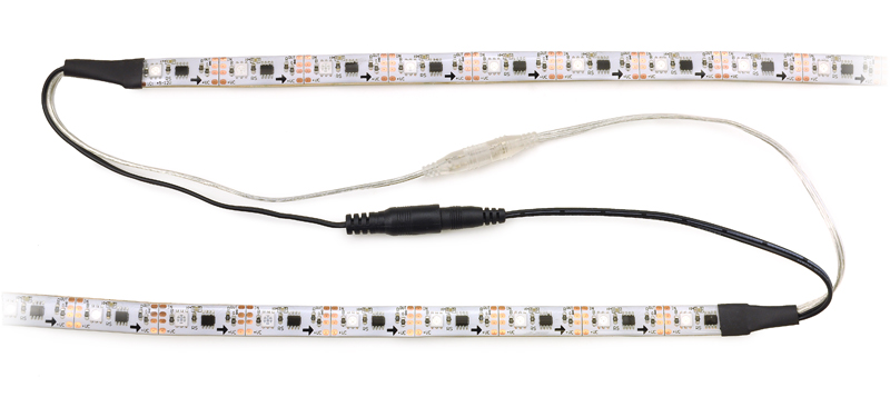 |
Two addressable RGB LED strips connected. |
|---|
With the 1 m and 2 m LED strips, it is possible to use a single power supply to power several strips by chaining their power connectors together (as long as the power supply can handle the combined current draw of the strips). However, this can result in a significant voltage drop between the beginning and the end of a long chain of strips, which will cause the brightness of the LEDs to vary noticeably down the length of the chain. We recommend chaining no more than 5 meters of strips with their power connectors. If you form a chain longer than this with the strips’ data connectors, you should power each five-meter section separately.
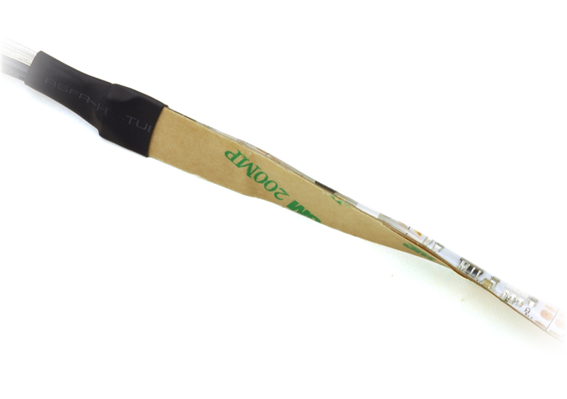
Cutting
The LED strip is divided into segments, with each 33.3 mm segment containing one RGB LED and its driver chip. The strip can be cut apart on the lines between each segment to separate it into two usable shorter sections. To access the connections on either side of the cut, you can peel away the epoxy on the front or the adhesive on the back to expose four copper pads. The data connection is labeled OUT or IN, the positive power connection is labeled +VC, and the two pads in the middle are both connected to ground.
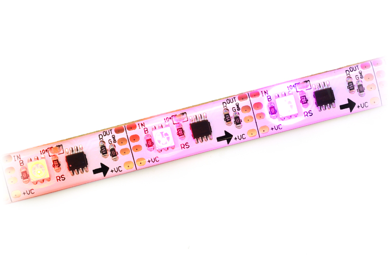 |
Addressable RGB LED strip segments. |
|---|
Protocol
These LED strips are controlled by a high-speed one-wire protocol.
The default, idle state of the signal line is low. To update the LED colors, you need to transmit a series of high pulses on the signal line. Each high pulse encodes one bit: a short pulse (0.7 μs) represents a zero, while a long pulse (1.3 μs) represents a one. The time between consecutive rising edges should be 2.5–9.0 μs. After the bits are sent, the signal line should be held low for 24 μs to send a reset command, which makes the new color data take effect. Our tests indicate that the pulse widths do not have to be precise: there is a threshold around 1 microsecond that determines whether the pulse is a 0 or a 1, and a wide range of pulse widths on both sides of the threshold will work.
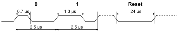 |
Low-speed addressable RGB LED strip data timing diagram (products #2540, #2541, and #2542 only). |
|---|
The color of each LED is encoded as three LED brightness values, which must be sent in RGB (red-green-blue) order. Each brightness value is encoded as a series of 8 bits, with the most significant bit being transmitted first, so each LED color takes 24 bits. The first color transmitted applies to the LED that is closest to the data input connector, while the second color transmitted applies to the next LED in the strip, and so on.
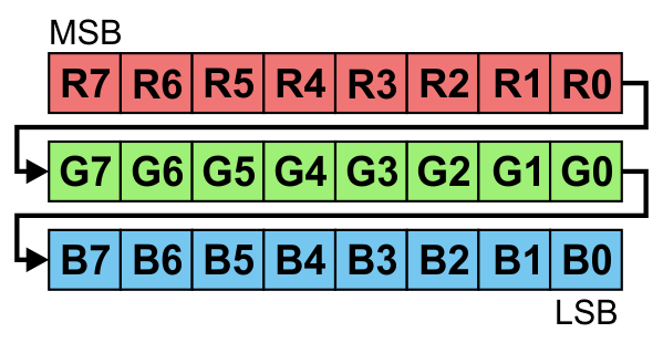 |
24 bits in RGB order represent the color of one LED. |
|---|
To update all the LEDs in the strip, you should send all the colors at once with no pauses. If you send fewer colors than the number of LEDs on the strip, then some LEDs near the end of the strip will not be updated. For example, to update all 30 LEDs on a 1-meter strip, you would send 720 bits encoded as high pulses and then hold the signal line low for 24 μs. If multiple strips are chained together with their data connectors, they can be treated as one longer strip and updated the same way (two chained 1-meter strips behave the same as one 2-meter strip).
Each RGB LED is controlled by a driver IC that receives data on its data input line and passes data on to the next IC using its data output line. The high-speed protocol of the driver allows for fast updates; our library for the Arduino below takes about 2.0 ms to update 30 LEDs, so it is possible to update a chain of several LED strips faster than 60 Hz. However, constant updates are not necessary; the LED strip can hold its state indefinitely as long as power remains connected.
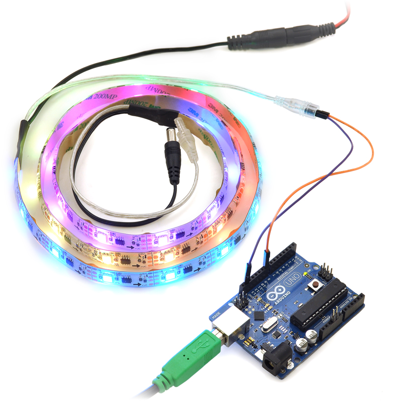 |
Controlling an addressable RGB LED strip with an Arduino. |
|---|
Implementing the protocol on a microcontroller
Since this LED strip does not use a standard protocol, a software bit-banging approach is usually needed to control it from a microcontroller. Because of the sub-microsecond timing, the bit-banging code generally needs to be written in assembly or very carefully optimized C, and interrupts will need to be disabled while sending data to the LED strip. If the interrupts in your code are fast enough, they can be enabled during periods where the signal line is low.
Sample code
To help you get started quickly, we provide sample code for several microcontroller platforms:
Related products


Home | Forum | Blog | Support | Ordering Information | Lists | Distributors | BIG Order Form | About | Contact
© 2001–2026 Pololu Corporation
