LPR510AL Dual-Axis (Pitch and Roll or XY) Gyro with ±100°/s and ±400°/s Ranges

This gyroscope board is a basic carrier/breakout board for the ST LPR510AL dual-axis gyro, which measures the angular rates of rotation about the pitch (x) and roll (y) axes. Two separate analog voltage outputs for each axis provide angular velocity ranges of ±100°/s and ±400°/s. This board has a 3.3V regulator for easy integration with 5V parts, includes a low-pass filter on each output for noise reduction, and is smaller than competing products, all at a lower price.
Alternatives available with variations in these parameter(s): axes measurement range Select variant…
| Description | Specs (8) | Pictures (8) | Resources (4) | FAQs (0) | On the blog (0) | Distributors (0) |
|---|
Discontinuation notice These dual axis gyros have been discontinuned. We recommend the L3GD20H 3-axis gyro as an alternative.
 |
 |
Overview
These two-axis gyros are essentially carrier boards or breakout boards for ST’s LPR510AL, LPY510AL, LPR550AL, and LPY550AL MEMS (micro-electro-mechanical systems) gyroscopes; we therefore recommend careful reading of the the corresponding datasheets (listed under the “resources” tab) before using these products.
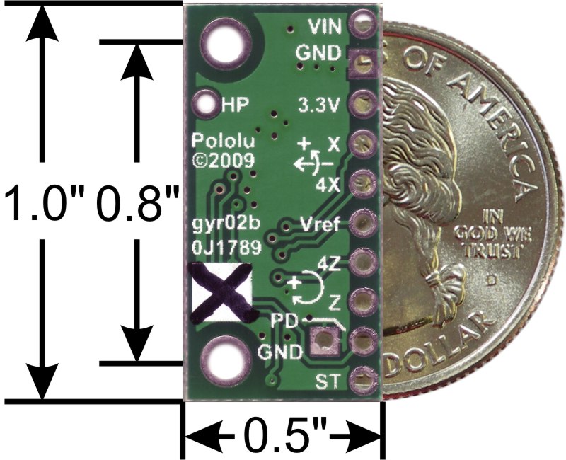
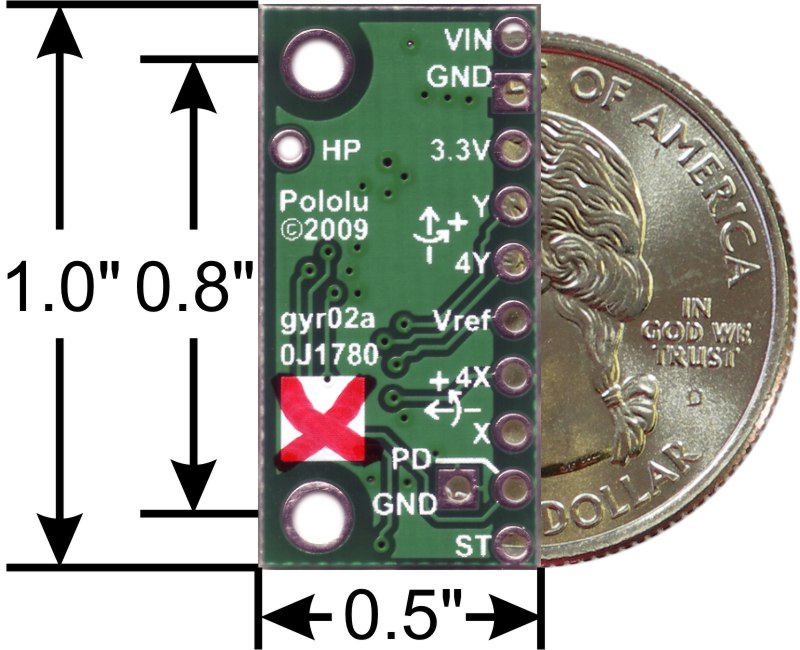
These parts are all members of ST’s latest family of dual-axis gyroscopes that differ only in their sensitivities and axes of rotation. Boards marked with a black X on the bottom silkscreen have ±100°/s and ±400°/s ranges; boards marked with a red X have ±500°/s and ±2000°/s ranges (each chip provides two sensitivities per axis—1x and 4x—and both are brought out to the user I/O on these carrier boards).
Although these are great ICs, their small, leadless packages make them difficult for the typical student or hobbyist to use. They also operate at 2.7 V to 3.6 V, which can make interfacing difficult for microcontrollers operating at 5 V. These carrier boards address both issues while keeping the overall size at half a square inch.
Features
- Integrated 3.3V regulator means no extra parts are required for integration into 5V systems.
- Assorted sensitivities from ±100°/s to ±2000°/s available.
- Optional power-down input; may be shorted to a neighboring ground pin if the low-power state is not needed.
- Optional embedded self-test input; this is connected to a pull-down resistor on the board to disable it by default.
- Two-stage low-pass filtered output to reduce high-frequency noise.
- Two mounting holes (0.086", intended for #2 screws) for sturdy connection to a robot chassis or project enclosure.
- Small size: 0.5" × 1.0".
Using the sensor
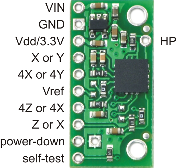 |
The axes of rotation are pitch (x) and roll (y) for LPR5x0AL parts and pitch and yaw (z) for LPY5x0AL parts; the relevant axes are indicated on the board silkscreens (shown above). The LPR versions are particularly well-suited for balancing robots with vertical PC boards since one axis can provide tilt-related information and the other can provide heading information. The LPY version can be used in pairs with one unit perpendicular to the other to make a flat three-axis gyro (this can also be achieved using one LPY and one LPR).
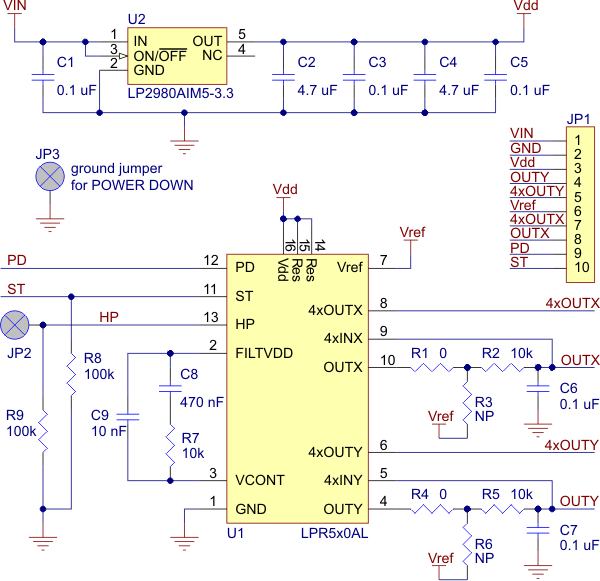
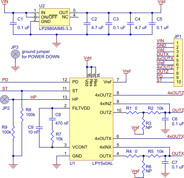
The schematics for the LPR5x0AL and LPY5x0AL gyroscope carriers are shown below. The devices can be powered directly through the Vdd/3.3V pin using a supply that is within the gyro chips’ acceptable power supply range of 2.7 V to 3.6 V. Alternatively, the boards can be powered by higher voltages, up to 16 V, using the VIN pin, which connects to a low-dropout 3.3V regulator. In this configuration, the 3.3V pin can serve as an output to be used as a reference voltage or power source for other low-power devices (up to around 50 mA, depending on the input voltage). Please note that unlike some other gyros and accelerometers, the outputs are not ratiometric with the Vdd/3.3V power line (i.e. at zero rate of rotation, the output should equal Vref, not half of the Vdd/3.3V supply).
The power-down pin is not connected by default. It must be driven low for the gyro to operate. If a low-power state is not required for your application, use a small piece of wire or solder to make a short between the power-down pin and the ground (square) pin next to it. To use the power-down pin, your circuit must bring it up to Vdd (typically 3.3 V); in 5V applications, this can be done by adding a pull-up resistor to the 3.3V output.
The self-test input is pulled low by default. To activate the self-test feature, drive the line to Vdd (the same pull-up trick as above can be used for 5V applications).
 |
For 5V microcontroller applications, the power down and self test lines should not be driven high. Instead, the microcontroller I/O pin can emulate an open-drain or open-collector output by alternating between low output and high-impedance (input) states. Put another way, if you are using a 5 V microcontroller, you should make your power down and self test I/O lines inputs and use pull-up to 3.3 V if you want them to be high. It is always safe for you to drive these lines low.
The output is an RC-filtered analog voltage that ranges from 0 to Vdd; with no rotation, the output voltage is typically 1.23 V regardless of Vdd. For 5V applications, the 3.3V output can be used as a reference for analog-to-digital converters to gain full resolution samples. Otherwise, your conversions will be limited to 66% of the full range (e.g. an 8-bit ADC will yield numbers from 0 to 168).
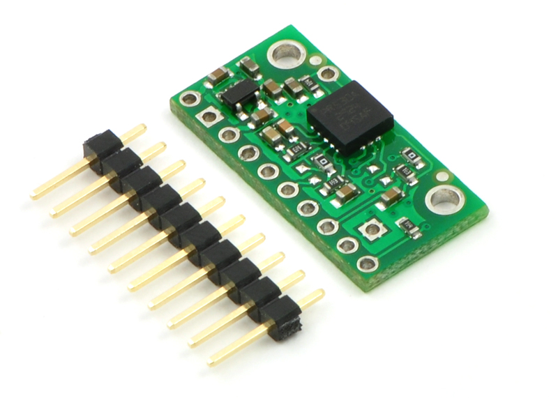
The gyro boards ship with a 1×10 0.1" breakaway male header strip (as shown in the picture to the right) that can be used for connecting custom cables or premium jumper wires or for plugging into perfboards or breadboards.
|
|
Related products


Home | Forum | Blog | Support | Ordering Information | Lists | Distributors | BIG Order Form | About | Contact
© 2001–2026 Pololu Corporation
