Pololu RC Switch with Small Low-Side MOSFET (rcs02a)

This is the original version of our RC switch with small low-side MOSFET, which features an integrated small, low-side MOSFET that can be used to drive small loads (up to around 3 A), such as a relay, when the switch is on. This board has been replaced by a newer version that is better in almost every way and should be a drop-in replacement in most cases.
| Description | Specs (6) | Pictures (6) | Resources (0) | FAQs (0) | On the blog (0) | Distributors (0) |
|---|
Note: We have released a newer version of the RC Switch with Small Low-Side MOSFET, which is better than this product in almost every way and should be a drop-in replacement in most cases. This product is now only available by large-volume special order. Please contact us for more information.
Overview
 |
The Pololu RC switch with small low-side MOSFET can be used with standard hobby radio control systems for radio control switch applications or simple interface applications. Example applications include converting extra RC receiver or servo controller outputs to simple high/low signals that can control LEDs or bigger MOSFETs or relays and connecting RC systems to microcontroller projects that do not have the necessary resources for decoding the RC interface. Two outputs indicate the presence of a valid signal and whether the switch is on or off, and an integrated low-side MOSFET turns on when the switch is on, allowing the board to drive small loads directly. The switch also features a flyback (or freewheeling) diode across the drive outputs so that you can connect a coil to them, such as a motor or relay, without any additional external components.
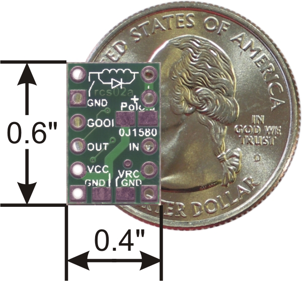
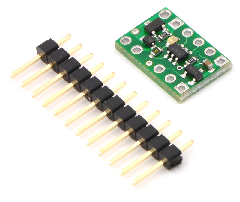
This compact unit measures a mere 0.4" x 0.6" and weighs just 0.5 g (0.02 oz) without the included header pins.
We offer a version of this RC switch without a MOSFET for applications that just require a low-current digital signal and a version with a medium-sized MOSFET for applications that require the device to switch larger loads.
Using the RC Switch
Connections
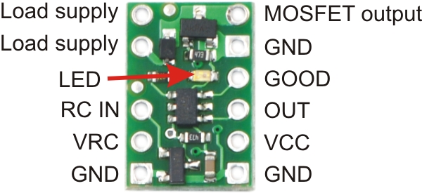 |
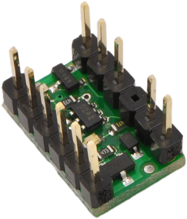
The lower-left side of the PCB (as shown to the right) contains three pins that can connect directly to an RC receiver or servo controller, and the four pins on the lower right side of the PCB are the board’s power supply connections and digital outputs. These outputs will be at the same levels as the VCC power connection, which can range from 2.0 V to 5.5 V. VCC is also the gate voltage that is used to turn the MOSFET on, so it should be noted that lower VCC voltages will lead to higher MOSFET on resistances (which in turn limits the maximum current the device can switch). The RC signal input pin, RC IN, can handle voltages from 0 to 7 V, and the threshold for a logic high is approximately 1 V.
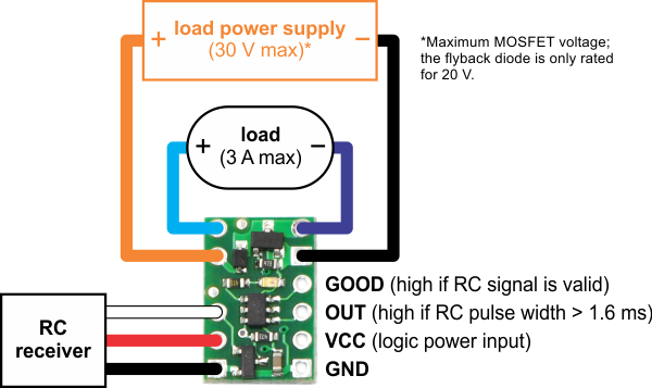
The load power supply and the load itself can be connected via the pins near the top of the board, with the positive side of the load on the left and the negative side of the load on the right. The negative load supply should connect to the ground pad on the top-right side of the board, and the negative side of the load itself should connect to the pin labeled “MOSFET output”. The two pins labeled “Load supply” are internally connected and intended to give you convenient connection points for both your load and your load power supply. There is a flyback (also known as a “freewheeling”) diode between the MOSFET output and load supply, which allows you to safely connect an inductive load such as a motor or relay. The MOSFET can deliver up to 3 A with VCC at 5 V; the performance will be worse if the input voltage is lower or if the MOSFET isn’t kept cool. The MOSFET can tolerate voltages as high as 30 V, but the flyback diode is only rated for 20 V, so an external diode should be used for load voltages that can exceed 20 V. If an external diode is used, the load supply pins should not be used; these connections should be made off of the board.
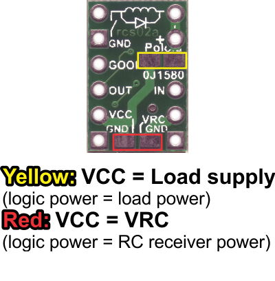 |
The VCC pin can be connected to the RC supply, VRC, by shorting across the pads on the back side of the PCB marked by the red box in the picture to the right, allowing either the RC receiver to power the digital device or allowing the digital system to power the RC receiver. If the connection between the two power pins is not made, VRC can be left disconnected since it is not used by the RC switch board.
The VCC pin can also be connected to the load supply by shorting across the pads on the back side of the PCB marked by the yellow box in the picture to the right, allowing either the load supply to power the digital device or allowing the digital system to power the load.
 |
Outputs and Indicator LED
The board has two digital outputs, each of which is capable of sourcing or sinking 20 mA. The primary output, OUT, goes high (on) when a valid signal is detected and the pulse width is above the threshold of 1.6 ms. There is approximately ±0.1 ms of hysteresis on the threshold, meaning that the pulse width will have to get to approximately 1.7 ms before the output turns on, and once on, the signal will have to fall below 1.5 ms to turn off. A secondary digital output, GOOD, indicates the presence of a valid RC signal (10-100 Hz pulse rate, 0.5-2.5 ms pulse width).
An LED on the RC switch indicates the status of the RC signal (and outputs). When a valid RC signal is not detected (GOOD and OUT both low), the LED flashes with a duty cycle of approximately 50% (i.e. the LED is on for as long as it is off). When a valid signal is detected but the pulse width is below the threshold (GOOD high and OUT low), the LED flashes at a very low duty cycle (i.e. very short flashes). When a good signal is detected and the pulse width is above the threshold, both outputs are high, the LED turns on (no flashing), and the MOSFET is on.
Included Hardware
A 12-pin 0.1" straight breakaway male header is included with the Pololu RC switch with small low-side MOSFET, which can be used to connect the RC switch to perfboards or breadboards.
|
|
Related products


Related categories


Home | Forum | Blog | Support | Ordering Information | Lists | Distributors | BIG Order Form | About | Contact
© 2001–2026 Pololu Corporation
