Pololu Blog » Posts tagged “community projects” »
Posts tagged “community projects” (Page 3)
You are currently viewing a selection of posts from the Pololu Blog. You can also view all the posts.
Popular tags: community projects new products raspberry pi arduino more…
Creepy eyes Halloween prop upgrade

There are only a couple days left in our Halloween sale! Visit the sale page for more information, and if you are in need of some inspiration, check out our Halloween-tagged blog posts for some sample projects, including this upgrade to my creepy eyes prop:
 |
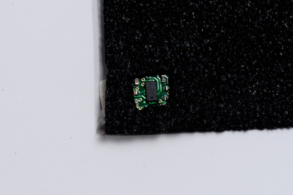
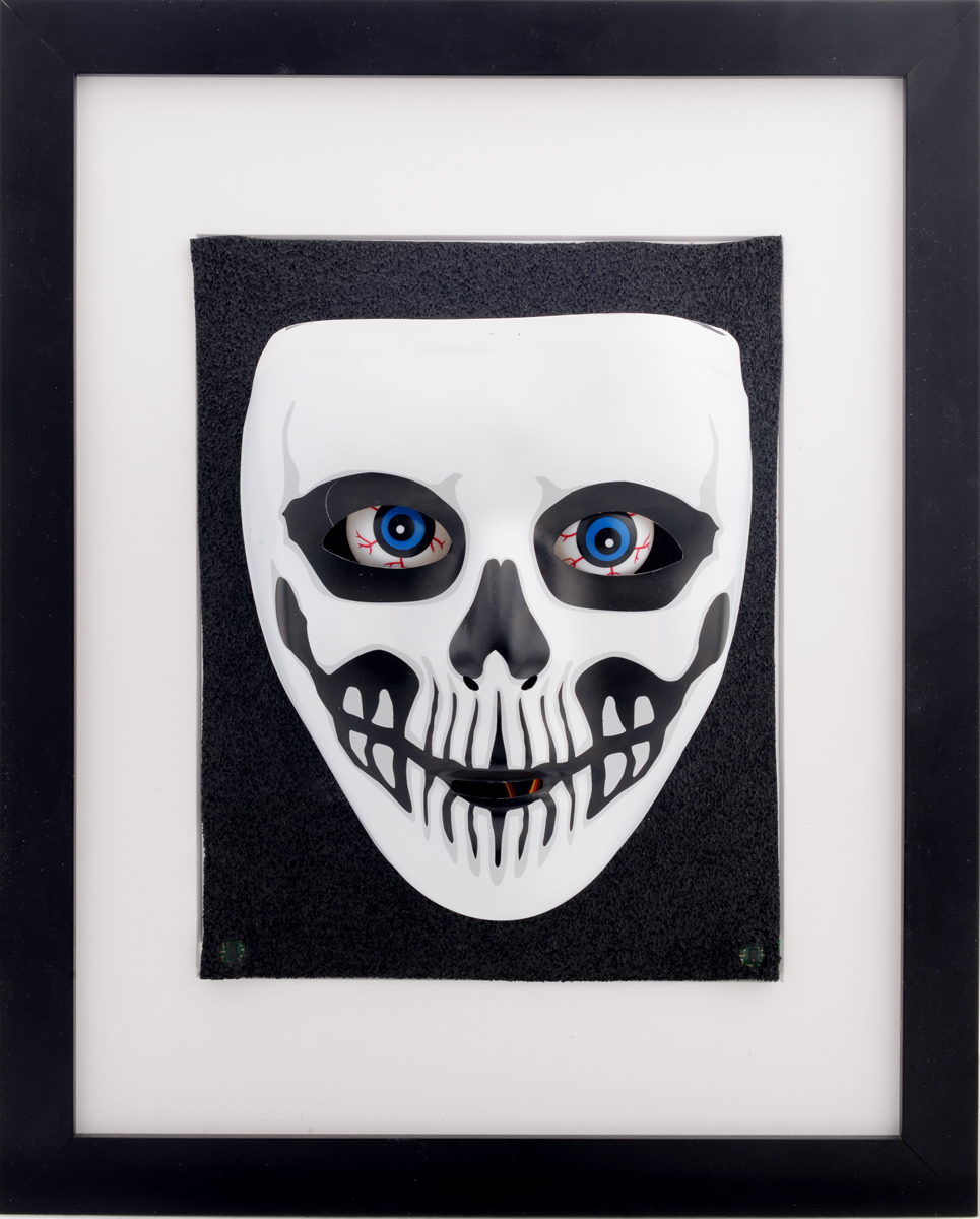
I finally got around to upgrading my creepy eyes Halloween prop. As shown above, I mounted the mask on a picture frame to make it more presentable. I also added some of our VL53L0X time-of-flight distance sensor carriers so that the eyes could follow people in front of the mask. I camouflaged the sensors behind the black layer of foam behind the mask. Below is an image showing how the sensors were hidden in the lower corners of the picture frame:
 |
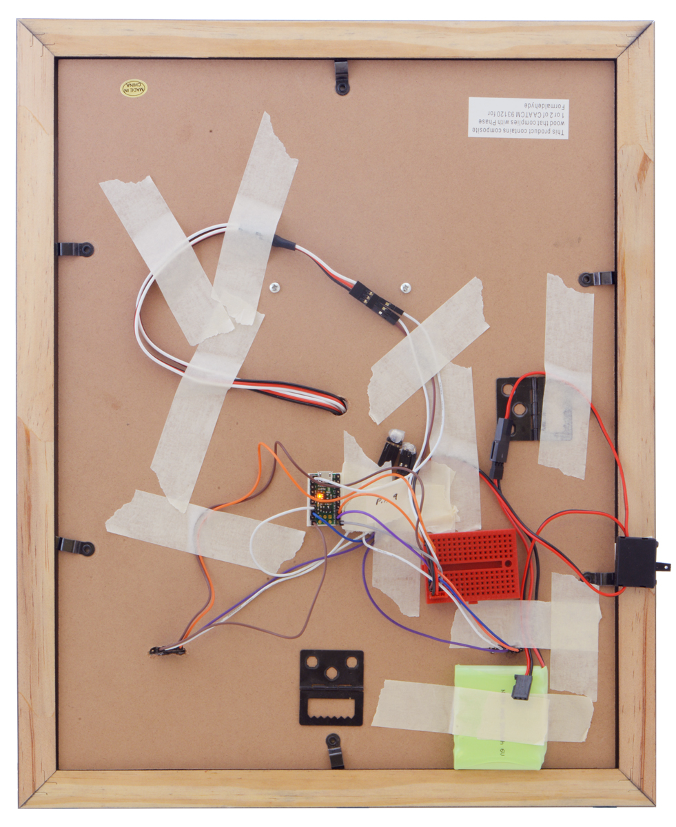
I also swapped the Maestro out for an A-Star 32U4 micro, so I could communicate with the sensors through I²C. Due to switching to the A-star micro, I added one of our small solderless breadboards to help distribute power and a servo Y splitter cable since both sub-micro servos can use the same signal. I also added a power switch and used some of our premium jumper wires to make connections. You can see all the electronics taped to the back of the picture frame in the picture below.
|
|
Related products


RC crawling skeleton

Our Halloween sale is still going strong! Visit the sale page for more information, and if you are in need of some inspiration, check out our Halloween-tagged blog posts for some sample projects, like this simple RC crawling skeleton that I made:
 |
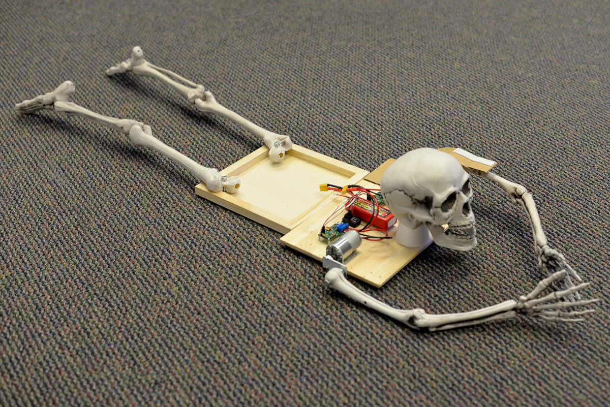
The setup for this project is pretty straightforward: a hobby RC transmitter sends signals through its receiver to a pair of Simple Motor Controllers, which each control a 37D mm gearmotor. The motors mount to a wooden base with a pair of L-brackets and connect to skeleton arms via universal aluminum mounting hubs and a short length of aluminum plating. The offset created by the aluminum plating causes the skeleton to move in a way that makes it look like it is slowly inching towards its next victim!
 |
A 3S LiPo provides power to the system through a pair of XT60 connectors, and the RC connections are made through some spliced female-female premium jumper wires. A black T-shirt covers up the electronics and a pair of cardboard “shoulder pads” help ensure the tee does not get tangled up in the rotation of the arm-bones.
|
|
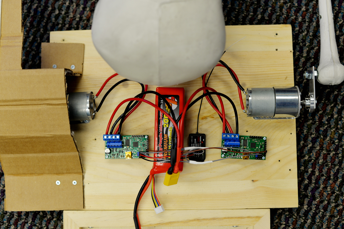
In practice, the crawling skeleton is more amusing than scary: it crawls really slowly and the sound of the motors turning is too industrial/mechanical to haunt anyone’s dreams. The sound is, however, loud enough to startle any unsuspecting friends!
Related products


SK9822 LED jack-o-lantern

To kick off our 2018 mini-series of spooky Halloween projects, I’ll go over how I fixed and modified my family’s broken light-up jack-o-lantern, but first I want to remind you that our Halloween sale is still going on. Visit the sale page for more information, and if you are in need of some inspiration, check out our Halloween-tagged blog posts for some sample projects. Now, on to the jack-o-lantern…
 |
The lantern suffered from a couple of burnt out incandescent bulbs and an unreliable power switch. The switch had a poor mechanical connection somewhere, which meant that in addition to sliding it into the “on” position, the case had to be pressed/squeezed in just the right spot to connect power. I absolutely needed to replace the switch, but in addition, this was a good time to upgrade from a bland set of incandescent lights to a more customizable lighting solution by adding some individually addressable RGB LEDs.
I wanted to preserve the battery-powered functionality of the lantern, and since it is powered by 4 C batteries, it has a supply voltage that could be anywhere between about 4V and 6V. The SK9822 LED strips that I wanted to use run on 5V, so I would need some kind of regulator to power them, as well as a microcontroller to send them control signals. Fortunately, our A-Star Mini microcontrollers have onboard regulators that allow them to work with a wide operating range of voltages, and provide ample current that can be used for other devices in the system, like the SK9822. In particular, the A-Star Mini LV was a good fit for a system like this with a voltage that started above 5V and could drop below it as the batteries were drained. (That A-Star’s regulator can also provide about 1A of current!)
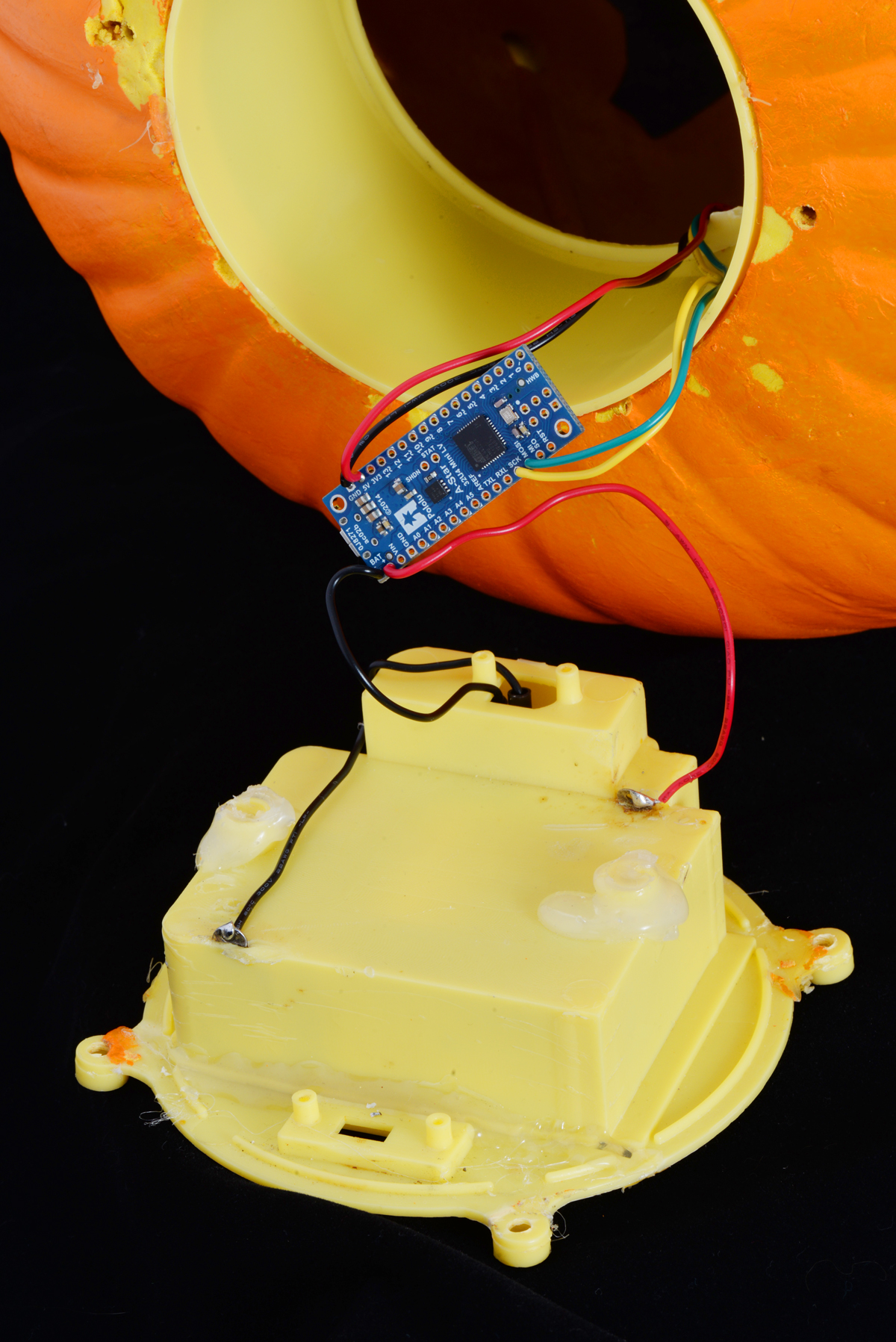 |
The A-Star mini LV and its connections. |
|---|
Starting the upgrade was pretty straightforward: remove all of the old hardware (the mess of old rusty wiring, the incandescent bulbs, and the switch), and solder in the A-Star to the battery holder terminals. From there, I soldered in a rocker switch that was much more satisfying to flip on and off than the older nonworking slide switch. Finally, I soldered up the four connections to the LED strip.
 |
The SK9822 LED strip segment taped to the outside of the plastic holder piece, as seen from the back of the jack-o-lantern. |
|---|
The strip itself only used 4 LEDs, since the lantern illuminates well and I didn’t want to unnecessarily consume lots of power (especially because the lantern was battery powered). The 4 piece segment was cut from one of the low density 30 LEDs per meter strips. The lower density meant that the LEDs were spaced out farther apart, which was useful to spread the LEDs across the plastic tube on the inside of the lantern and more evenly distribute the light. Our LED strip library made it easy to get started programming!
Another benefit of this hardware upgrade is the ability to reprogram the lighting display to whatever I want. Also, since the LED strips use so few IO pins, the decoration is in a good state to add additional electronics (like a proximity sensor or MP3 trigger)!
Related products


PyTic - Python interface for Pololu Tic Stepper Motor Controllers
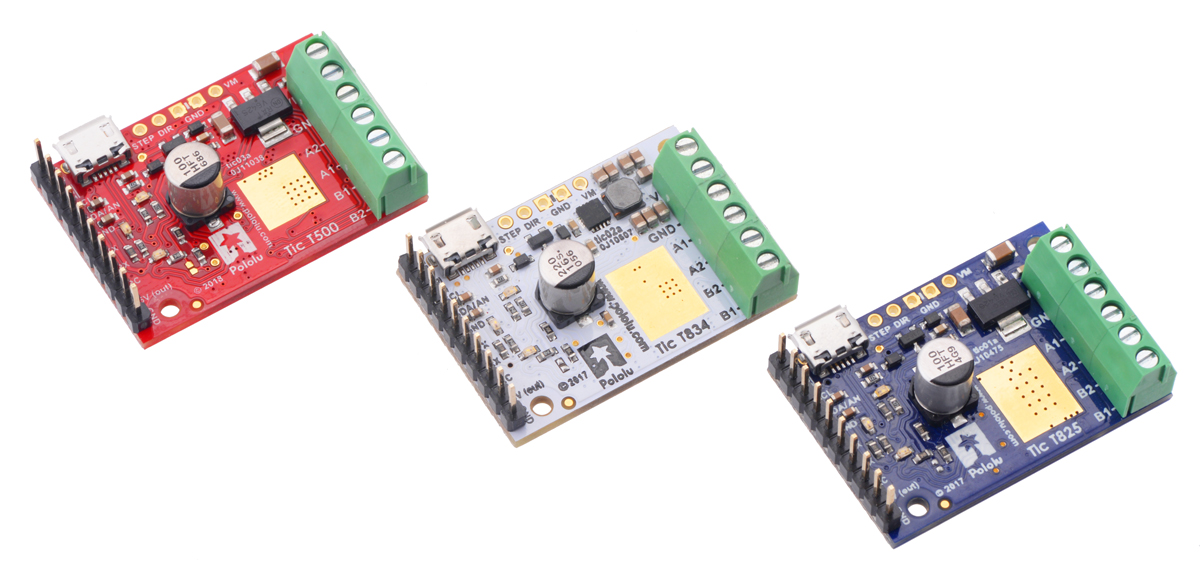 |
Customer Daniel Castelli of the Allen Institute has released a Python package for interfacing with our Tic Stepper Motor Controllers. Currently, he only supports 64-bit Windows, but the source code is available and should be straightforward to extend to other operating systems. Here is example code using PyTic to control a stepper motor:
import pytic
from time import sleep

# - Initialization -------------------------------------------

tic = pytic.PyTic()

# Connect to first available Tic Device serial number over USB
serial_nums = tic.list_connected_device_serial_numbers()
tic.connect_to_serial_number(serial_nums[0])

# Load configuration file and apply settings
tic.settings.load_config('path\\to\\config.yml')
tic.settings.apply()

# - Motion Command Sequence ----------------------------------

# Zero current motor position
tic.halt_and_set_position(0)

# Energize Motor
tic.energize()
tic.exit_safe_start()

# Move to listed positions
positions = [1000, 2000, 3000, 0]
for p in positions:
  tic.set_target_position(p)
  while tic.variables.current_position != tic.variables.target_position:
    sleep(0.1)

# De-energize motor and get error status
tic.enter_safe_start()
tic.deenergize()
print(tic.variables.error_status)
The code and documentation for this package are available on GitHub.
Related products


Modified Han Solo toy blaster controls LED displays of Star Wars characters
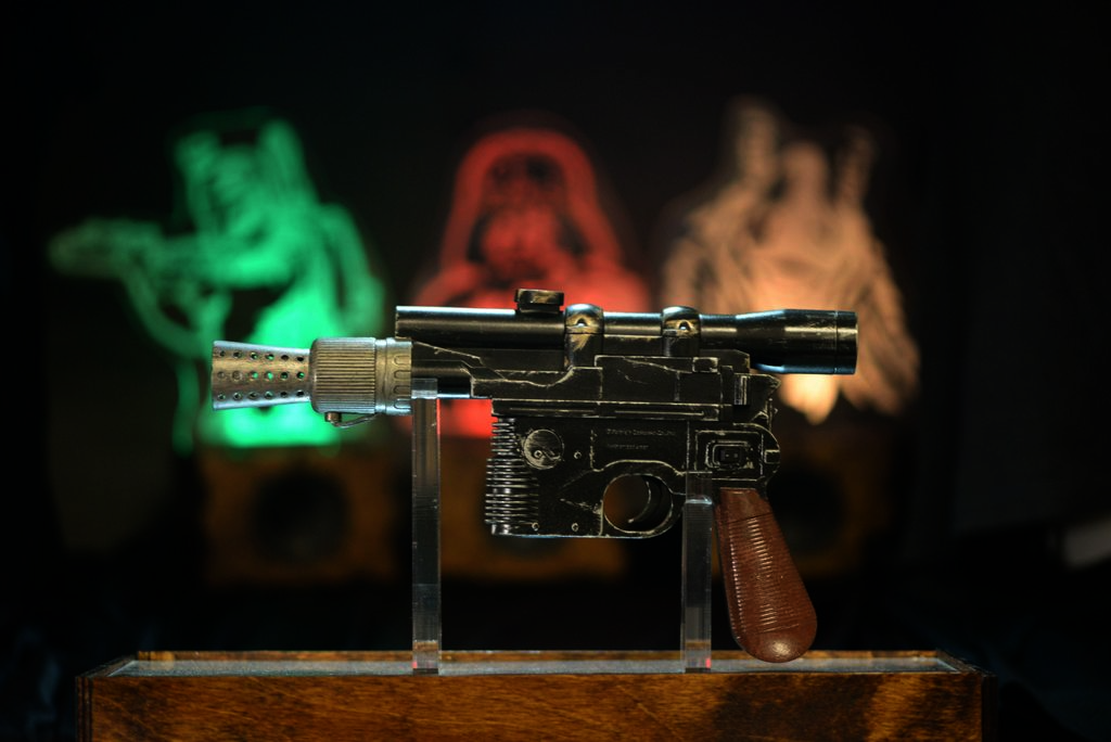 |
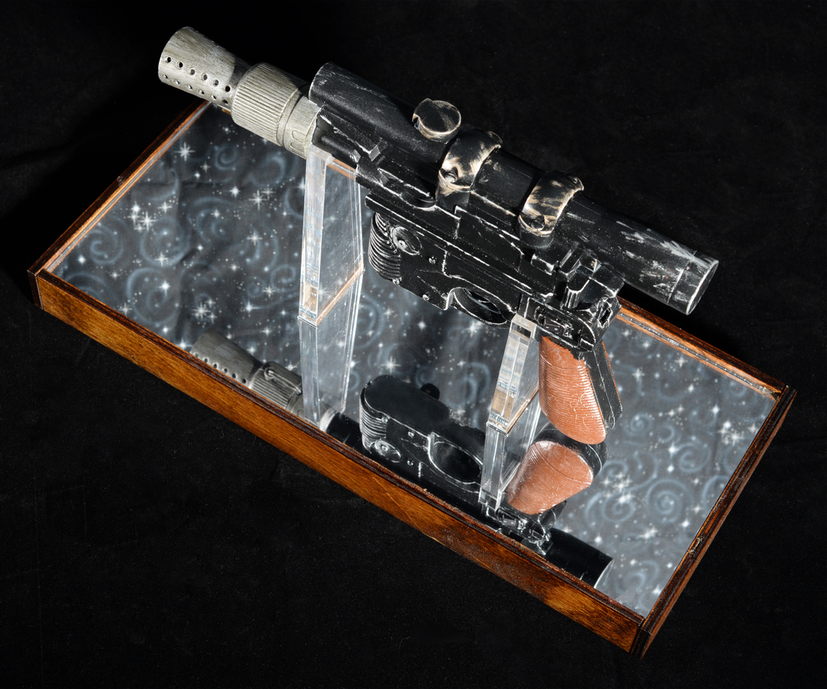
A while ago, I made a wedding gift for some friends, both of whom are avid Star Wars fans. The gift was basically a multi-piece decorative set that consisted of a modified toy Han Solo blaster, a stand to hold the blaster, and three edge-lit LED displays: one each of Boba Fett, Darth Vader, and Jar Jar Binks. I painted over the toy blaster to make it look more like it came straight out of the movies and added electronics so that it could interact with the displays (and the couple’s TV!).
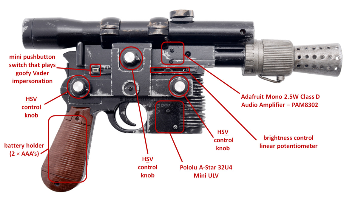
The blaster uses IR TV remote codes to do several things: it can shoot the LED displays (and they’ll respond by blinking and playing audio recordings unique to each character), change the color and brightness of each display, and it can act as a limited TV remote by turning on or off the TV. At the heart of the blaster lies an A-Star 32U4 Mini ULV, which monitors the state of a switch, a couple of buttons, and a few potentiometers in order to decide which actions to carry out. The ULV version of the A* Mini is especially convenient for this setup because the toy blaster was originally powered by two AAA batteries, which produce too low of a voltage for a 5V microcontroller. The ULV’s built-in switching step-up voltage regulator allows it to operate directly off of the batteries and power the other components, unlike typical Arduinos that need at least 7V.
|
|
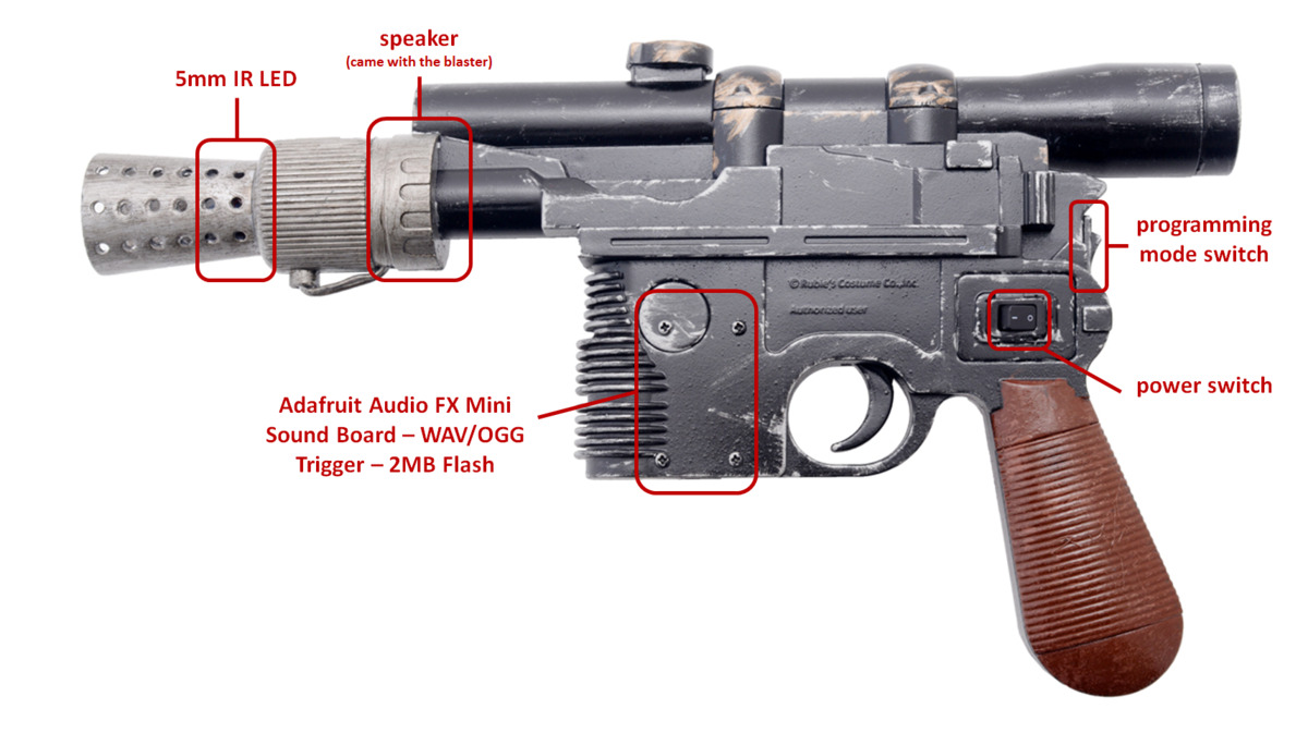
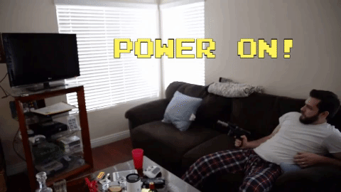
The blaster has two modes: one for shooting the displays and turning on/off the TV and another for adjusting color and brightness of the displays. Which mode the blaster is in is determined by the state of the programming mode switch, which is accessible with a flick of the thumb. While powered on, the A* continually checks to see if the programming mode switch is enabled. If it is disabled, the blaster will respond to trigger presses. When the trigger is depressed, the A* does two things: it sends a pulse train to a 5mm IR LED and drives an input pin low on an Adafruit Audio FX Mini sound board, which then outputs sound to a speaker through a 2.5W audio amplifier, producing DL-44 blaster firing noises. The blaster and displays use the IRremote Arduino library for sending and receiving the pulses. For these blaster shots, the blaster emits the IR TV remote code that corresponds to the generic power-on/power-off code for an LG TV. This same code is decoded by the Star Wars displays as a “hit” and the characters react to being shot. You can watch videos of those reactions in the YouTube playlist below (the playlist also includes the displays’ bonus Easter egg content, which is only accessible by sending certain button presses from the LG TV remote!). The sound level is a little low, so you might need to increase your volume to hear what the characters are saying:
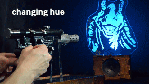
If the programming mode switch is enabled, the blaster repeatedly emits a set of IR TV remote codes that contain information on what color and how bright the displays should be. Color is adjusted in the HSV color space using the blaster’s three rotary potentiometers (one each for hue, saturation, and value). There is also a linear potentiometer that can be used to set overall brightness (this effect combines with the change in brightness from adjusting the value potentiometer). So long as a display’s IR receiver can detect the IR signal sent by the blaster, the LED information can be decoded and the LED arrays can be updated.
 |
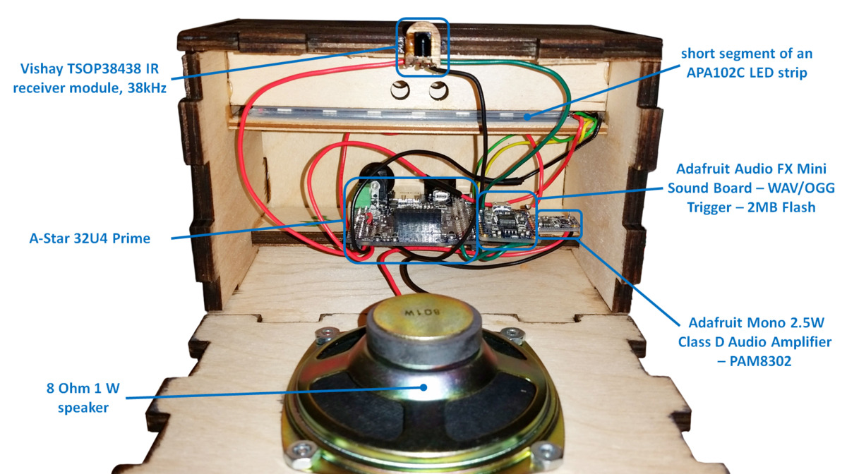
Each display features a ~12″ tall profile of the head or upper body of a Star Wars character. The profiles are laser-etched onto a 1/2″ thick clear acrylic piece, which also has holes at its base. The holes allow the piece to be fastened to a recessed channel at the top of the display box. A short segment of an APA102C LED strip lines the bottom of the recessed channel and faces upward into the acrylic profile, which allows its light to disperse across the laser-etched surfaces. The display box has the same sound board and amplifier as the blaster, but uses a more powerful 1W speaker. An A-Star 32U4 Prime controls everything and power is supplied via a 9V 3A wall power adapter.
 |
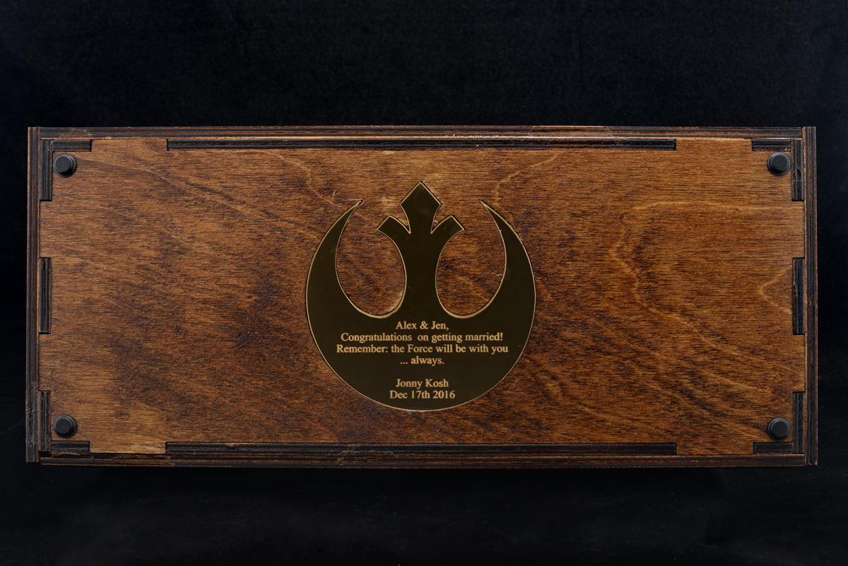
Compared to the rest of the system, the design of the blaster stand is pretty straightforward: it is just several pieces of 1/4″ plywood arranged into a frame that houses two channels. Those two channels have mounting holes which allow two clear acrylic pieces, which conform to the shape of the blaster, to be fixed to the frame. A lip along the inside of the frame makes it easy to mount the silver mirrored acrylic piece. The bottom of the mount features a personal well-wish from me to the couple. The message is written on the inside of the Alliance Starbird, which is cut from gold mirrored acrylic. The stand also houses some scrap metal parts (a bunch of prototype Zumo blades) to give it some weight. Four adhesive rubber feet, one for each corner of the stand, help make sure the stand doesn’t slide around easily and scrape the gold Starbird piece.
|
|
I owe a part of the inspiration of this gift to my coworker, Kevin, since in some ways I was basically trying to one-up his Harry Potter-themed wedding gift, which was given to another coworker, Brandon, for his wedding. Kevin also ended up helping me make some good decisions and generate some clean-looking CorelDraw files for the display cutouts/rastering. So, thanks, Kevin! You the real MVP.
For more pics, gifs, and a build log, check out this Imgur album! Also, you can find 2D (.DXF and .CDR) and 3D (.STL, .STEP, and .SLDPRT) CAD files for the laser cut parts on my Thingiverse page!
 |
Related products


UNLV wins 1st place in Student Design Competition at ASME E-Fest West
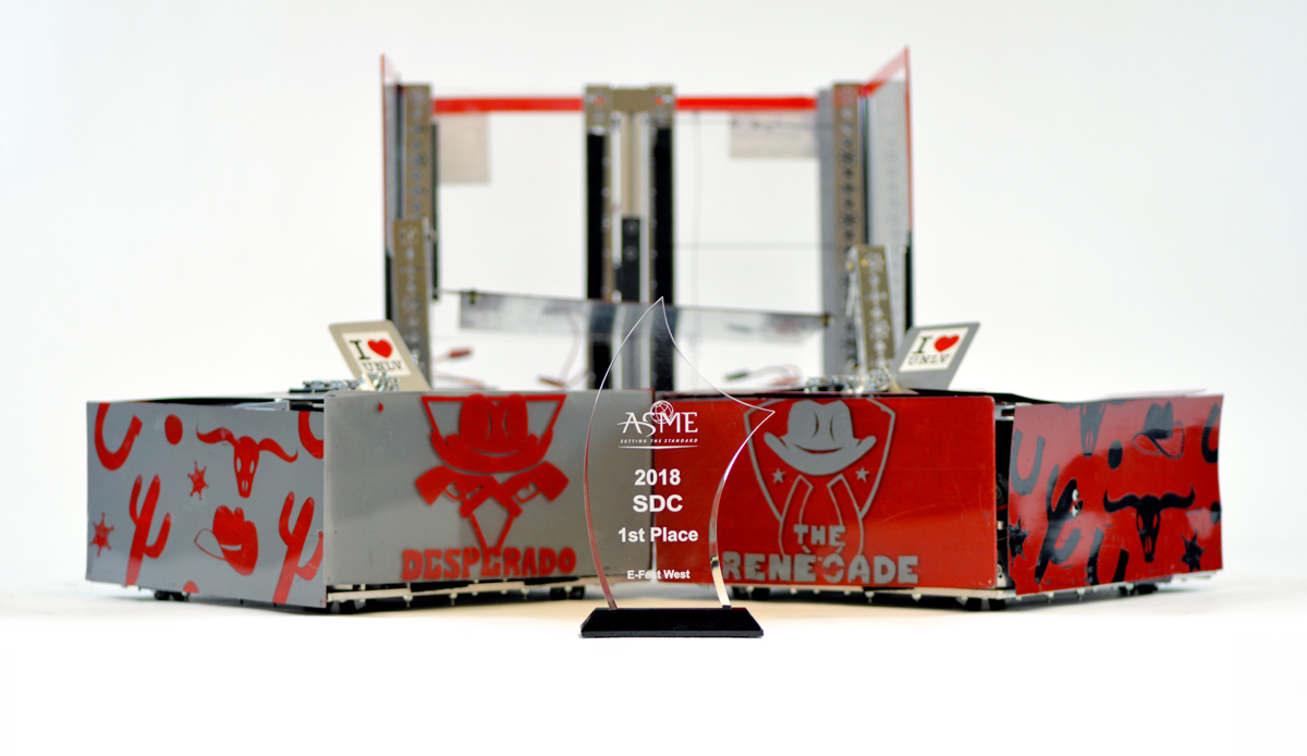 |
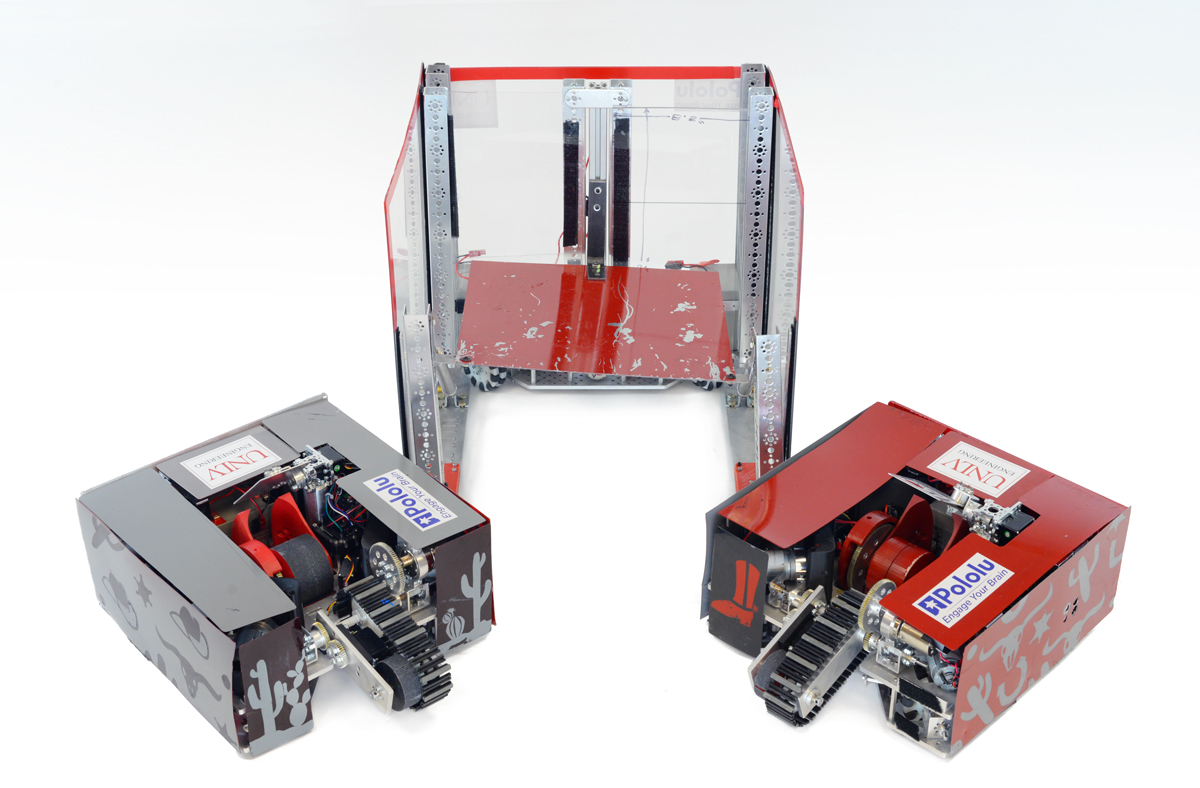
At Pololu, I have spent the recent weeks developing new products, like the motor driver I announced on Wednesday, but at school (I am a mechanical engineering student at the University of Nevada, Las Vegas, UNLV) I have been managing an American Society of Mechanical Engineers (ASME) Student Design Competition (SDC) team. SDC teams create robotic devices to fulfill a problem statement that changes every year. They compete with their devices at one of ASME’s regional student conferences called E-Fests. Last year, I managed a three-member team that built The Rebel WIP and earned third place in the Robot Pentathalon at the E-Fest West. This year, my ten-member team made a squad of robots called The Rebel Bandits for the new SDC challenge, Robot Football. We overcame many technical challenges and 14 other teams to win first place at this year’s E-Fest West that competed this past Saturday!
The SDC’s Robot Football was loosely based on soccer, but with four robot teams competing to shoot eight tennis balls into four goals on a 5 m x 5 m field. Each team was assigned a goal to defend, and eight tennis balls were set in a square pattern at the center of the field for robots to score into the other goals. For this competition, teams could build multiple remote controlled robots, but the robots and controllers had to be able to fit inside a single 50 cm cube. Some teams built soccer squads with only two or three big robots, while other teams used up to six little robots for their squad (which made the matches super chaotic), but each team could only control one ball at a time. Robots controlling a ball needed to keep the ball on the ground when they moved around, but they could stop and lift the ball to shoot on a goal.
 |
The Rebel Bandits. |
|---|
 |
The Outlaw. |
|---|
I am really proud of the robots my team designed and built for this competition, so I want to share how my team made a first place robot squad! However, since we won the competition at E-Fest West, we were invited to compete again in the SDC Finals at ASME’s International Mechanical Engineering Congress and Exposition in Pittsburgh, Pennsylvania this November. We will be competing against the first and second place winners from the other student conferences: E-Fest East, E-Fest Asia Pacific, and E-Fest South America, as well as the SDC team from California State University, Northridge, who came in second place at E-Fest West. The teams will be more competitive, and the prize money increases significantly! So that makes me a little bit nervous about showing all the technical details for our robots right now, but I would still like to give a basic rundown.
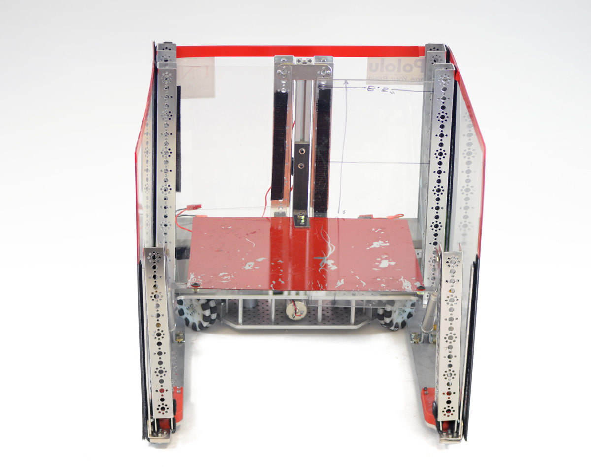
Our strategy was to build three large robots: one defender, and two offensive robots. We call the defender robot The Outlaw. It is built on a U-shaped frame with 19 in (48.3 cm) long sides and has tall walls. Even though it cannot block from inside our penalty box and is not particularly fast, it can seriously impede the efforts of other teams to score on our goal just by being big and tall. The Outlaw uses three DC motors for its drive train at the base of the U-frame, and Pololu ball casters help support the far ends of the U-frame. One DC motor is driven by a G2 High-Power Motor Driver, and since we use an A-Star 32U4 SV for the Outlaw’s microcontroller, the other two DC motors are driven by a Dual G2 High-Power Motor Driver Shield for Arduino.
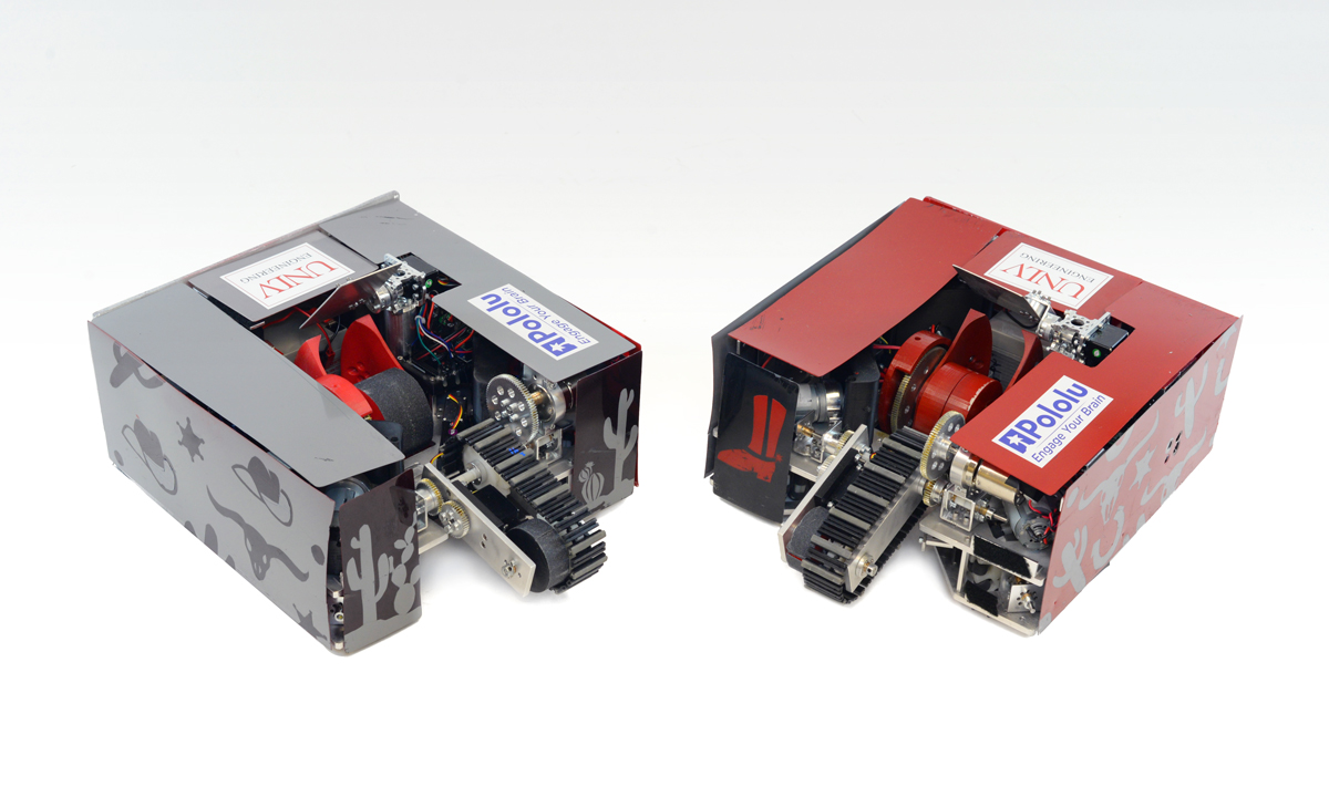 |
The Desperado and The Renegade. |
|---|
The two offensive robots are named The Renegade and The Desperado (you should notice the Wild West theme by now). Other than the color schemes, these robots are almost complete duplicates. We decided to build only two offensive robots because it gave us sufficient space to build robust robots with high quality shooting mechanisms.
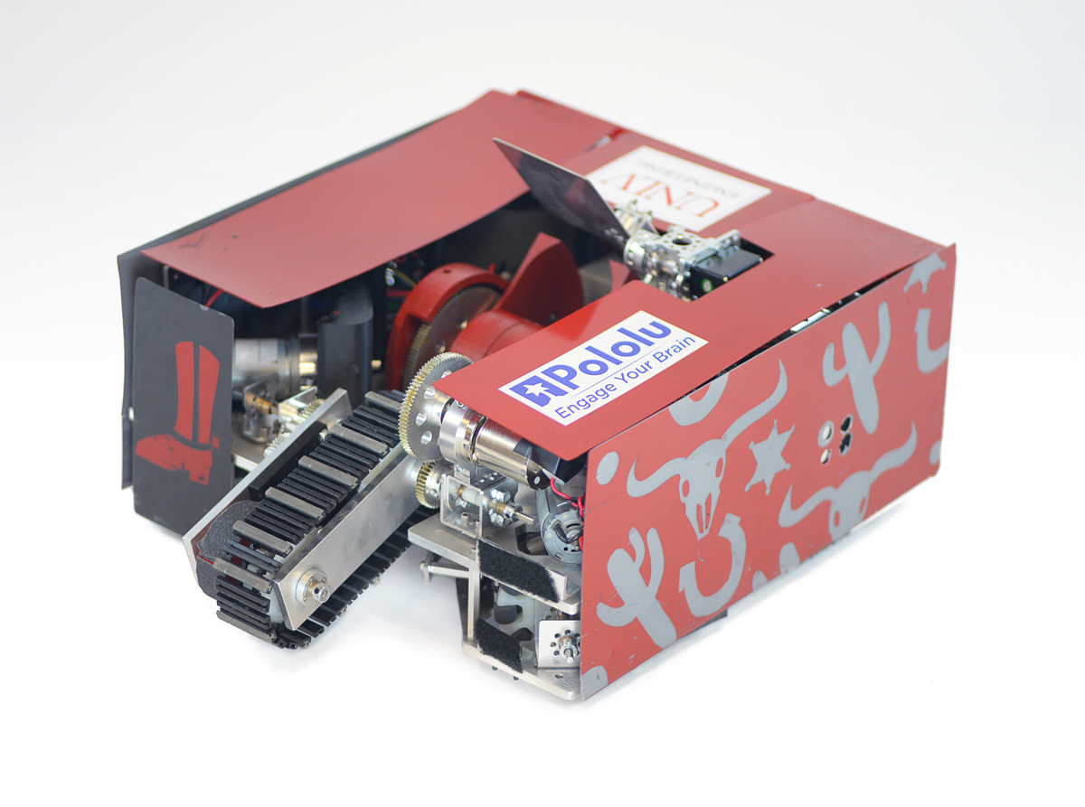 |
Each offensive robot uses four DC motors for the drive train. A standard size servo extends an arm with an intake belt, and a DC motor runs the intake belt to pull a ball into the robot’s reservoir. Another servo opens and closes a gate that keeps the ball in the reservoir or pushes the ball into the shooting mechanism. The reservoir allows the ball to roll on the ground as the robot moves without the intake belt constantly pushing down on the ball and impeding driving. The shooting device is a ramp and flywheel. When taking a shot on the goal, the operator stops the robot and the flywheel revs up to high speed. Then the gate servo pushes the ball into the ramp. The velocity of the wheel pulls the ball along the ramp structure and throws the ball at high velocity. Just beyond the outlet for the ball, a plate on a pivot controlled by a servo lets us control the ball’s trajectory. This allows us to shoot across long distances or over defender robots.
The offensive robots each use an Arduino Mega as their primary microcontroller. Most of the DC motors on The Renegade and The Desperado are controlled by either a Dual G2 High-Power Motor Driver Shield connected to the Arduino Mega or are driven by individual G2 High-Power Motor Drivers. On each robot, a Maestro servo controller is used as a slave controller that powers and controls the standard servos. Additionally we use the Maestros’ functionality as general I/O controllers to send logic signals to the individual 18v17 Motor Drivers. In our setups, we want the servos and the Maestros to be powered from 6 V, so we use a step-down voltage regulator to connect the Maestro power rails to main power supply on each robot, a 12 V lead-acid battery.
I am very fortunate to have worked with an awesome team this year for the SDC, and I am grateful for the parts and support we obtained from both Pololu and UNLV! It was also exciting to see different teams at the competition using other Pololu parts like our wheels, metal gearmotors, regulators, and brushed DC motor drivers. After our SDC Finals competition in November, I plan to write another blog post about more of the technical details of our robot. (Hopefully I will be able to brag a little about another first place trophy too!)
 |
Patrick and 6 members of UNLV’s SDC team that traveled to competition in Pomona, California. |
|---|
Until then, I want to know more about some of your projects! I hope you will share a little about your cool projects in the blog comments, or you can make a Pololu forum account and post in the Share Your Projects category!
Related products


Beatty Robotics Curiosity rover replica
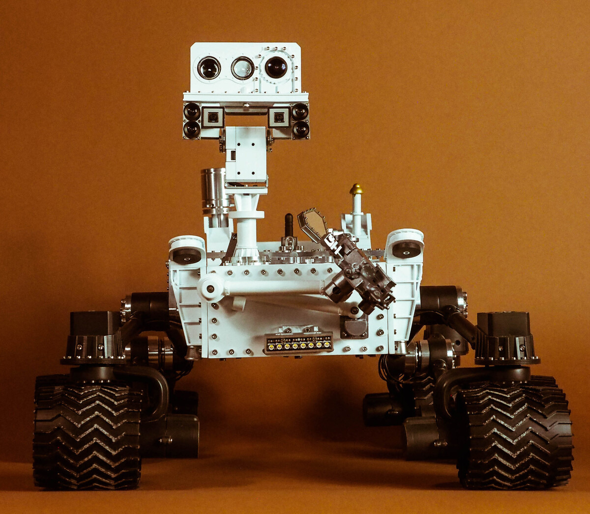 |
Our favorite team of robot-making sisters over at Beatty Robotics has finished making another stellar robot! Their latest creation is a 1/10th scale functional replica of Curiosity, the rover from NASA’s Mars Science Laboratory mission. The rover uses a variety of Pololu products, both mechanical and electrical. For example, it uses a pair of G2 high power motor drivers to control six 25D mm gearmotors, each of which is coupled to a wheel with a 4mm hex adapter. The robot also features our voltage regulators, current sensors, logic level shifters, and pushbutton power switches. In addition to using our products, the rover also uses some stainless steel parts cut with our custom laser cutting service.
The Beattys are currently in the process of documenting their rover. Right now there’s a blog post out focused on the robot’s exterior, but the duo plans to also post about the electronics and functionality soon. We are looking forward to seeing more pictures and learning about how each part contributes to the whole system!
If you are curious to know more about the electronics inside of this replica rover, you can keep an eye on the Beatty website, or you can stay tuned to our blog – we will update you when they share more.
Related products


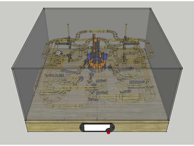
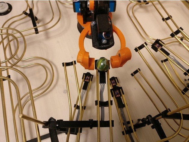
Maestro-controlled robot arm conducts rolling ball kinetic sculpture
Erik Pettersson’s interactive sculpture, Roball, is a gripping take on the classic rolling marble kinetic sculpture. Roball uses a robotic arm to pick up a small ball and randomly place it on one of five tracks, where it twists and turns as it rolls down the track, eventually coming to rest at a holding station. The input to the system is a single pushbutton, and when the user presses the button, the arm picks the ball up wherever it stopped. Then, the device randomly selects another path, moves the marble to the start of that track, and releases it. A 12-channel Maestro controls the whole system and analog sensors (which might be our QTR-1A) at each holding station at the end of each track help not only detect the ball, but help the Maestro randomize its next move. Because of the ball’s non-uniform surface, the analog sensor will read different values depending on how the ball is positioned. That reading is then used in a calculation to determine what track to roll the ball on next.
You can learn more about this project on its Thingiverse page.
|
|
Related products


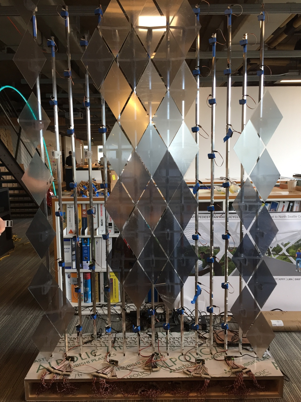
Five Mini Maestros control an interactive array of 98 mirrors
MIRR, which stands for Mobile Interactive Responsive Reflector, is an interactive installation that responds to people’s movement by independently rotating elements in its array of 98 mirrored panels. A FEETECH Mini Servo FT1117M actuates each panel and a total of five Mini Maestros control the servos. People can also use a custom box of arcade buttons to independently move each panel. You can read more about how MIRR works in this post on our forum.
|
|

Related products


Maestro animated pilot in RC model aircraft
 |
A Maestro commands this Luftwaffe pilot to direct his steely-eyed gaze out into the wild blue yonder. |
|---|
Klaus Herold, who makes RC models of World War II aircraft, used one of our Maestro servo controllers to elevate one of his German Luftwaffe models to new heights. A 6-channel Micro Maestro adds a touch of reality to his model by animating the movement of the head of the pilot. The movement has two degrees of freedom: the head rotates side to side and tilts up and down. Additionally, the cockpit canopy extends and retracts. You can see the pilot in action in the video below:
Related products


Home | Forum | Blog | Support | Ordering Information | Lists | Distributors | BIG Order Form | About | Contact
© 2001–2026 Pololu Corporation


