

This is a merged information page for Item #4733.
View normal product page.
Pololu item #:
4733
Brand:
Pololu
Status:
Active and Preferred

This tiny breakout board for the MPS MP6550 motor driver offers a wide operating voltage range of 1.8 V to 22 V and can deliver a continuous 1.7 A (2.5 A peak) to a single brushed DC motor. The MP6550 has built-in current sensing and current limiting as well as protection against under-voltage, over-current, and over-temperature conditions. The carrier board also adds reverse-voltage protection up to 20 V.
 Compare all products in Brushed DC Motor Drivers.
|
MP6550 Single Brushed DC Motor Driver Carrier. |
|---|
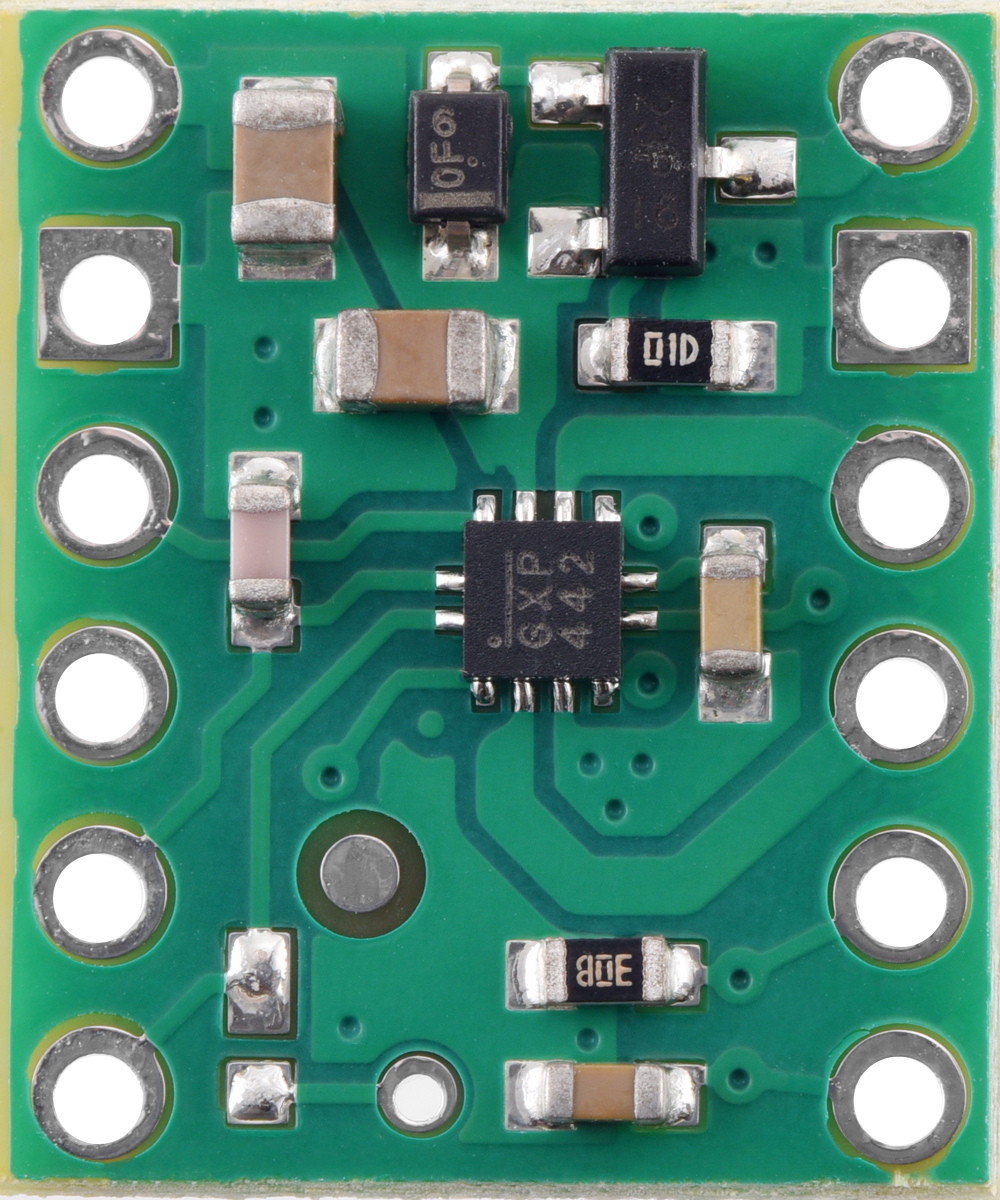 |
MP6550 Single Brushed DC Motor Driver Carrier, top view. |
|---|
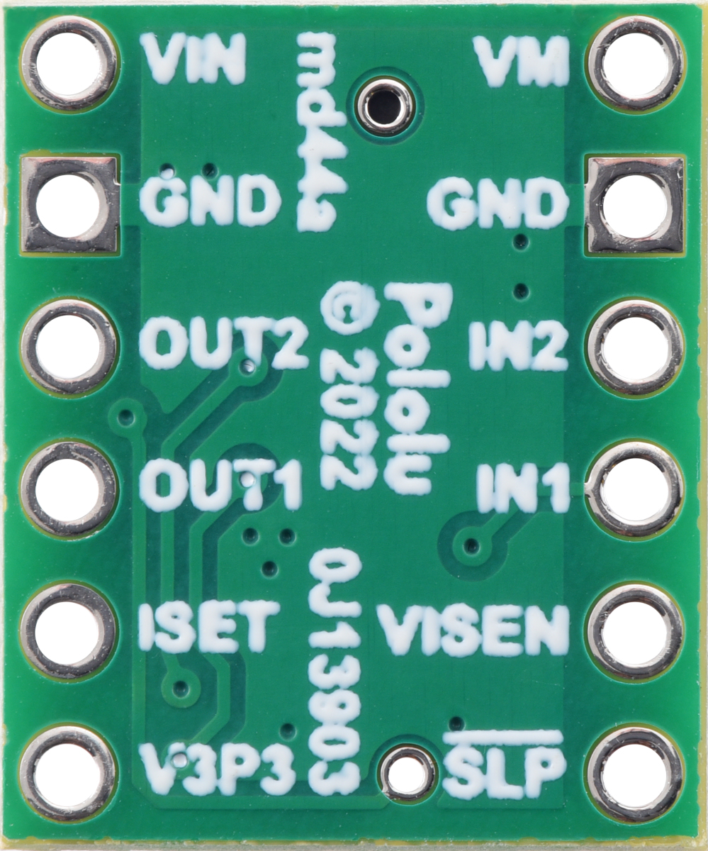 |
MP6550 Single Brushed DC Motor Driver Carrier, bottom view. |
|---|
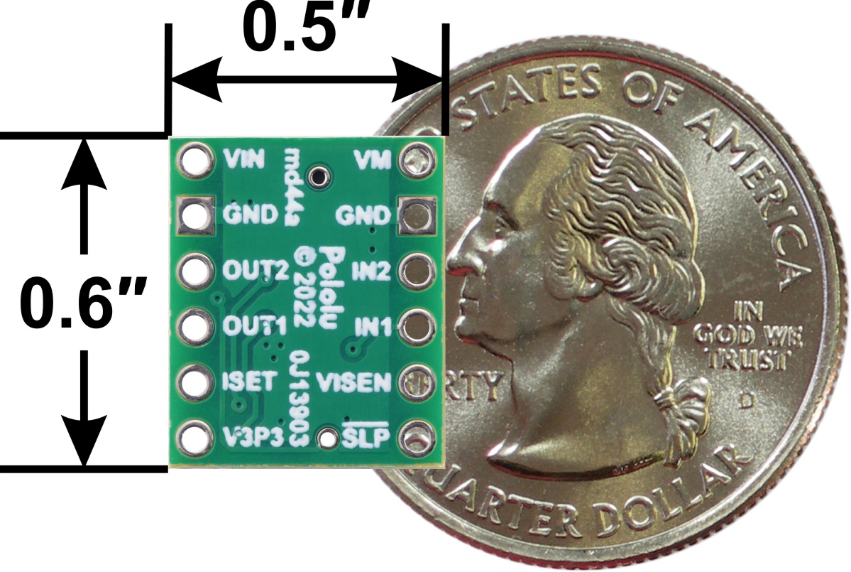 |
MP6550 Single Brushed DC Motor Driver Carrier, bottom view with dimensions. |
|---|
 |
MP6550 Single Brushed DC Motor Driver Carrier with included hardware. |
|---|
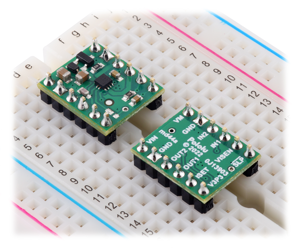 |
MP6550 Single Brushed DC Motor Driver Carriers in a breadboard. |
|---|
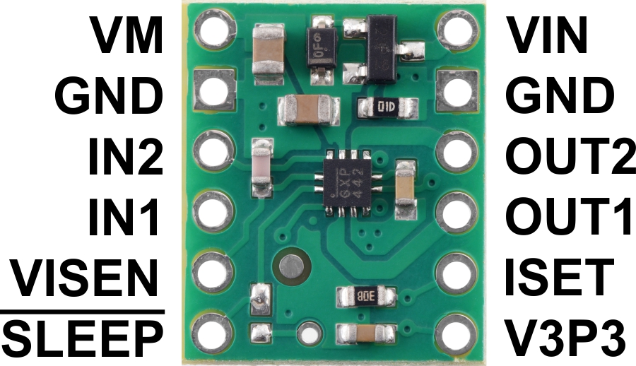 |
MP6550 Single Brushed DC Motor Driver Carrier, top view with labeled pinout. |
|---|
 |
Minimal wiring diagram for connecting a microcontroller to a MP6550 Single Brushed DC Motor Driver Carrier. |
|---|
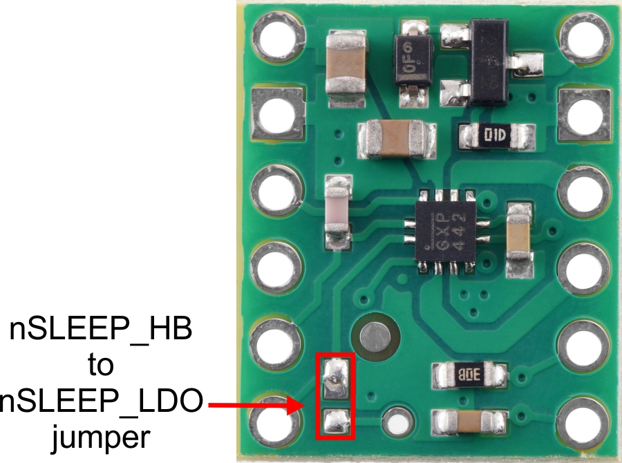 |
nSLEEP_HB to nSLEEP_LDO jumper on the MP6550 Single Brushed DC Motor Driver Carrier. |
|---|
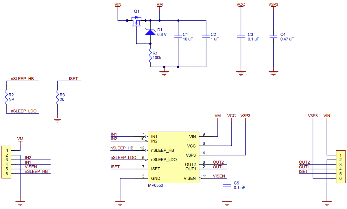 |
Schematic diagram for the MP6550 Single Brushed DC Motor Driver Carrier. |
|---|
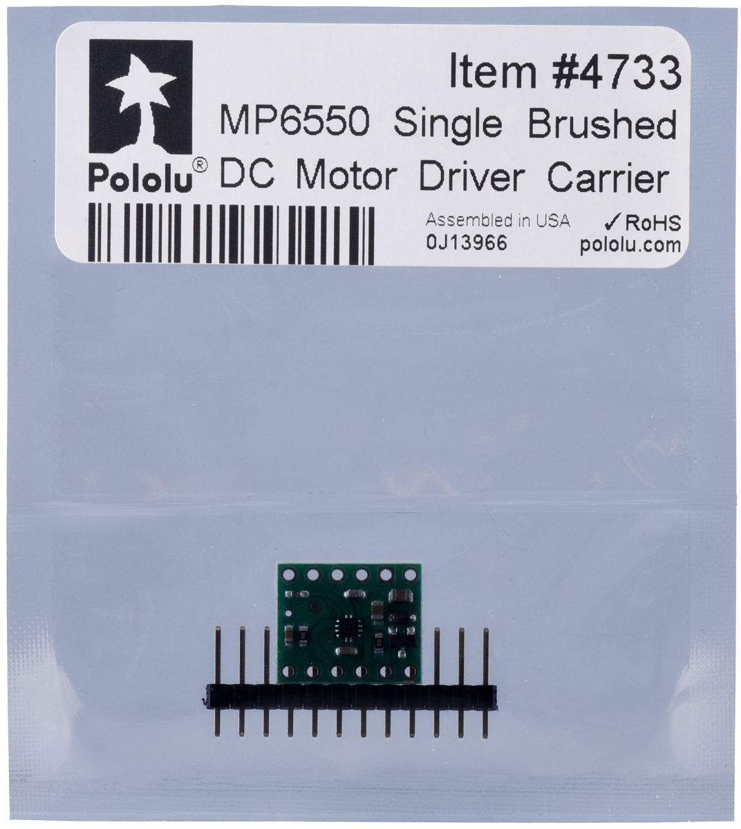 |
Standard packaging for the MP6550 Single Brushed DC Motor Driver Carrier. |
|---|
|
MP6550 Single Brushed DC Motor Driver Carrier, bottom view with dimensions. |
|---|
The MP6550 from Monolithic Power Systems (MPS) is an H-bridge motor driver IC that can be used for bidirectional control of one brushed DC motor at 1.8 V to 22 V. It can supply up to about 1.7 A continuously and features configurable current sensing and current limiting. Since this board is a carrier for the MP6550, we recommend careful reading of the MP6550 datasheet (714k pdf). The board ships populated with all of its SMD components, including the MP6550.
|
|
Two 1×6-pin breakaway 0.1″ male headers are included with the MP6550 motor driver carrier, which can be soldered in to use the driver with breadboards, perfboards, or 0.1″ female connectors. (The headers might ship as a single 1×12 piece that can be broken in half.) The right picture above shows the two possible board orientations when used with these header pins (parts visible or silkscreen visible). You can also solder your motor leads and other connections directly to the board.
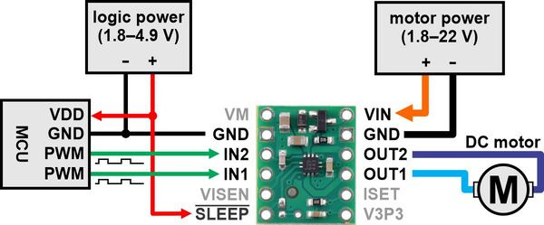 |
Minimal wiring diagram for connecting a microcontroller to a MP6550 Single Brushed DC Motor Driver Carrier. |
|---|
In a typical application, power connections are made on one side of the board and control connections are made on the other. Aside from motor and power connections (including a logic voltage connection to SLEEP), the only required control pins are IN1 and IN2.
The following simplified truth table shows how the driver operates:
| IN1 | IN2 | OUT1 | OUT2 | operating mode |
|---|---|---|---|---|
| 0 | 0 | Z | Z | coast (outputs off) |
| PWM | 0 | PWM (H/Z) | PWM (L/Z) | forward/coast at speed PWM % |
| 0 | PWM | PWM (L/Z) | PWM (H/Z) | reverse/coast at speed PWM % |
| PWM | 1 | L | PWM (L/H) | reverse/brake at speed 100% − PWM % |
| 1 | PWM | PWM (L/H) | L | forward/brake at speed 100% − PWM % |
| 1 | 1 | L | L | brake low (outputs shorted to ground) |
|
| PIN | Default State | Description |
|---|---|---|
| VIN | 1.8 V to 22 V board power supply input (reverse-protected up to 20 V). | |
| GND | Ground connection points for the motor and logic supplies. | |
| VM | This pin gives access to the motor power supply after the reverse-voltage protection MOSFET (see the board schematic below). It can be used to supply reverse-protected power to other components in the system. | |
| OUT1 | Motor output 1. | |
| OUT2 | Motor output 2. | |
| IN1 | LOW | Control input 1. PWM can be applied to this pin. |
| IN2 | LOW | Control input 2. PWM can be applied to this pin. |
| SLEEP | LOW | Sleep input that puts the MP6550 into a low-power sleep mode when low. By default, this pin is only connected to the nSLEEP_HB pin on the MP6550. It can also be connected to the nSLEEP_LDO pin to control the 3.3V LDO by bridging the nSLEEP surface mount jumper (see below). |
| ISET | Current sensing and current limiting configuration pin. A 2 kΩ resistor is connected from this pin to ground (see below). | |
| VISEN | Current sense output. This pin provides an analog current-sense feedback voltage of 200 mV/A by default (see below). | |
| V3P3 | 3.3 V regulator output. Disabled by default (see below). |
The board’s SLEEP pin is connected to the nSLEEP_HB pin on the MP6550, which is internally pulled low, disabling the H-bridge and putting the driver into a low-power sleep mode. This can be used to conserve power when the device is not in use. Driving SLEEP high enables the driver.
The MP6550 has an internal 3.3 V low-dropout (LDO) regulator, although it is not enabled by default since the chip’s nSLEEP_LDO pin, which controls the regulator, is also internally pulled low. (The LDO does not need to be enabled for the rest of the driver to function.) By default, nSLEEP_LDO is not connected to anything on the carrier board, but by shorting the surface mount jumper shown in the picture below, nSLEEP_LDO can be tied to the board’s SLEEP pin. This allows the LDO to be enabled along with the rest of the driver when SLEEP is high. When enabled, the 3.3V regulator can supply up to 50 mA of current through the V3P3 pin.
 |
nSLEEP_HB to nSLEEP_LDO jumper on the MP6550 Single Brushed DC Motor Driver Carrier. |
|---|
The MP6550 can sense the motor current and actively limit it by using constant-off-time PWM current regulation (current chopping). The feedback sensitivity and current limiting threshold are set by a resistance connected between the ISET pin and ground. The carrier board is populated with a 2 kΩ pull-down resistor on ISET, which makes the VISEN pin output a voltage of 200 mV/A and limits the current to 2.5 A by default. This behavior can be customized by adding an external pull-down resistor to the ISET pin in parallel with the one already on the carrier. This will reduce the overall resistance, increasing the current limit and decreasing the VISEN sensitivity. If you want to reduce the current limit and increase the VISEN sensitivity, you would need to remove the surface mount resistor and replace it with a surface mount or external resistor of a larger value. Refer to the MP6550 datasheet for more information about the driver’s current sensing and current limiting.
The MP6550 datasheet recommends a maximum continuous current of 2 A. However, the chip by itself will typically overheat at lower currents. In our tests, we found that for most combinations of logic (VCC) and motor supply (VIN) voltages, the chip was able to deliver 2 A for between 30 seconds and a few minutes before the chip’s thermal protection kicked in and disabled the motor outputs; a continuous current of 1.7 A was sustainable for many minutes without triggering a thermal shutdown.
The actual current you can deliver will depend on how well you can keep the motor driver cool. The carrier’s printed circuit board is designed to help with this by drawing heat out of the motor driver chip. Our tests were conducted at 100% duty cycle with no forced air flow; PWMing the motor will introduce additional heating proportional to the frequency.
This product can get hot enough to burn you long before the chip overheats. Take care when handling this product and other components connected to it.
|
Schematic diagram for the MP6550 Single Brushed DC Motor Driver Carrier. |
|---|
This schematic is also available as a downloadable pdf (90k pdf).
| Size: | 0.5″ × 0.6″ |
|---|---|
| Weight: | 0.5 g1 |
| Motor driver: | MP6550 |
|---|---|
| Motor channels: | 1 |
| Minimum operating voltage: | 1.8 V |
| Maximum operating voltage: | 22 V |
| Continuous output current per channel: | 1.7 A |
| Peak output current per channel: | 2.5 A2 |
| Current sense: | 0.2 V/A3 |
| Maximum PWM frequency: | 100 kHz |
| Minimum logic voltage: | 1.8 V |
| Maximum logic voltage: | 4.9 V4 |
| Reverse voltage protection?: | Y5 |
| Header pins soldered?: | N |
| PCB dev codes: | md44a |
|---|---|
| Other PCB markings: | 0J13903 |
This DXF drawing shows the locations of all of the board’s holes.
No FAQs available.
No blog posts to show.