

This is a merged information page for Item #2874.
View normal product page.
Pololu item #:
2874
Brand:
Pololu
Status:
Active and Preferred

This version of our DRV8834 Low-Voltage Stepper Motor Driver Carrier ships with male header pins installed, so no soldering is required to use it with an appropriate 16-pin socket or solderless breadboard. Please see the DRV8834 Low-Voltage Stepper Motor Driver Carrier product page for more information about the driver.
Alternatives available with variations in these parameter(s): header pins soldered? Select variant…
 Compare all products in 16-pin Stepper Motor Drivers or DRV8834 Low-Voltage Stepper Motor Driver Carriers.
|
DRV8834 Low-Voltage Stepper Motor Driver Carrier (Header Pins Soldered). |
|---|
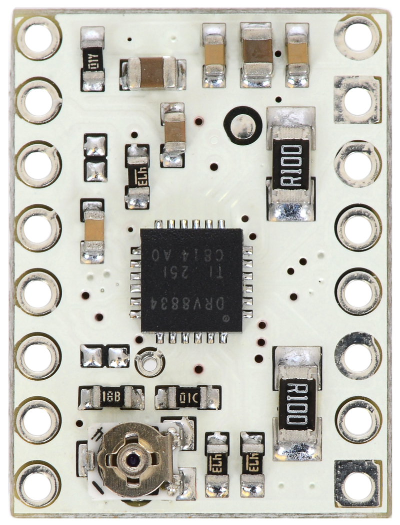 |
DRV8834 low-voltage stepper motor driver carrier. |
|---|
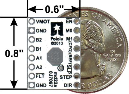 |
DRV8834 low-voltage stepper motor driver carrier with dimensions. |
|---|
 |
Schematic diagram for the DRV8834 low-voltage stepper motor driver carrier. |
|---|
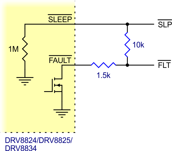 |
Schematic of nSLEEP and nFAULT pins on DRV8824/DRV8825/DRV8834 carriers. |
|---|
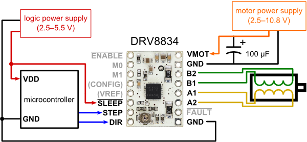 |
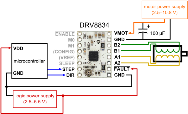
Minimal wiring diagram for connecting a microcontroller to a DRV8834 stepper motor driver carrier (1/4-step mode). |
|---|
 |
Alternative minimal wiring diagram for connecting a microcontroller to a DRV8834 stepper motor driver carrier (1/4-step mode). |
|---|
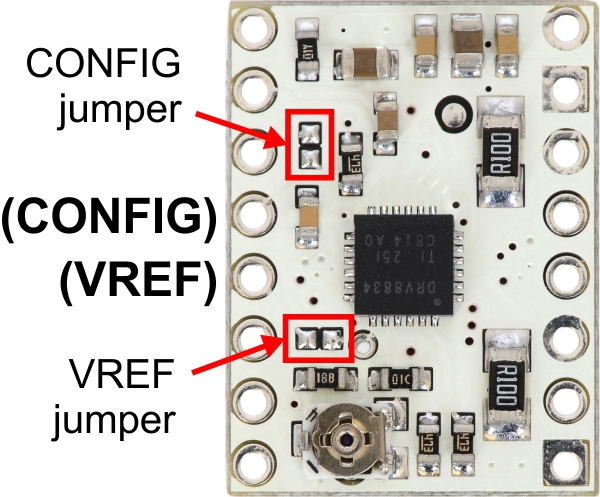 |
Jumpers for enabling optional CONFIG and VREF pins on the DRV8834 low-voltage stepper driver carrier. |
|---|
This version of our DRV8834 Low-Voltage Stepper Motor Driver Carrier ships with male header pins installed as shown in the main product picture, so no soldering is required to use it with an appropriate 16-pin socket or solderless breadboard. Please see the DRV8834 Low-Voltage Stepper Motor Driver Carrier product page for more information about the driver.
| Size: | 0.6″ × 0.8″ |
|---|---|
| Weight: | 2.5 g |
| Minimum operating voltage: | 2.5 V |
|---|---|
| Maximum operating voltage: | 10.8 V |
| Continuous current per phase: | 1.5 A1 |
| Maximum current per phase: | 2 A2 |
| Minimum logic voltage: | 2.5 V3 |
| Maximum logic voltage: | 5.5 V3 |
| Microstep resolutions: | full, 1/2, 1/4, 1/8, 1/16, and 1/32 |
| Reverse voltage protection?: | N |
| Header pins soldered?: | Y |
| PCB dev codes: | md22a |
|---|---|
| Other PCB markings: | 0J7097 |
Printable schematic diagram for the DRV8834 low-voltage stepper motor driver carrier.
This DXF drawing shows the locations of all of the board’s holes.
Texas Instruments product page for the DRV8834, where you can find the latest datasheet and additional resources.
This Arduino library, written by forum member laurb9, allows users to control a stepper motor with our A4988, DRV8825, DRV8834, and TB67S581FNG"-based carriers (for the TB67S581FNG, use the library code for the DRV8825 as the TB67S581FNG is Toshiba’s version of the DRV8825). The library has functions that enable users to set rotational rate, change microstepping mode, and specify how many steps to take or specify how many degrees to rotate.
No, a low-voltage stepper motor driver is not your only option. To avoid damaging your stepper motor, you want to avoid exceeding the rated current, which is 600 mA in this instance. All of our stepper motor drivers let you limit the maximum current, so as long as you set the limit below the rated current, you will be within spec for your motor, even if the voltage exceeds the rated voltage. (For example, driving a 3.9 V motor with a DRV8825, and using a supply voltage higher than the DRV8825’s minimum of 8.2 V, will not damage the motor as long as the current limit is set appropriately.)
The voltage rating is just the voltage at which each coil draws the rated current, so the coils of your stepper motor will draw 600 mA at 3.9 V. By using a higher voltage along with active current limiting, the current is able to ramp up faster, which lets you achieve higher step rates than you could using the rated voltage.
However, if you still want to use a lower motor supply voltage for other reasons, our DRV8834 or STSPIN-220 low-voltage stepper motor drivers are appropriate choices.
Yes, you do! Setting the current limit on your stepper motor driver carrier before connecting your motor is essential to making sure that it runs properly. An appropriate current limit also ensures that your motor is not allowed to draw more current than it or your driver can handle, since that is likely to damage one or both of them.
Setting the current limit on this stepper motor driver is done by adjusting the on-board potentiometer. We strongly recommend using a multimeter to measure the VREF voltage while setting the current limit so you can be sure you set it to an appropriate value (just turning the pot randomly until things seem to work is not a good approach). The following video has more details on setting the current limit:
Measuring the current draw at the power supply does not necessarily provide an accurate measure of the coil current. Since the input voltage to the driver can be significantly higher than the coil voltage, the measured current on the power supply can be quite a bit lower than the coil current (the driver and coil basically act like a switching step-down power supply). Also, if the supply voltage is very high compared to what the motor needs to achieve the set current, the duty cycle will be very low, which also leads to significant differences between average and RMS currents: RMS current is what is relevant for power dissipation in the chip but many power supplies won’t show that. You should base your assessment of the coil current on the set current limit or by measuring the actual coil currents.
Please note that while the DRV8834 driver IC is rated for up to 2.2 A (peak) per coil, its overcurrent protection might kick in at as low as 2 A, and the chip by itself will overheat at lower currents. We have found that it generally requires a heat sink to deliver more than approximately 1.5 A per coil, but this number depends on factors such as ambient temperature and air flow. For example, sealing three DRV8834 driver carriers in close proximity in a small box will cause them to overheat at lower currents than a unit by itself in open air.
No blog posts to show.