

This is a merged information page for Item #1928.
View normal product page.
Pololu item #:
1928
Brand:
Generic

This crimping tool can be used to crimp both male and female versions of our Tamiya connector crimp pins, mini Tamiya connector crimp pins, JST RCY connector crimp pins, JR crimp pins, Futaba J crimp pins, and crimp pins for 0.1″ housings onto 16-28 AWG wires to make custom cables. The crimping die has a width of 7 mm, and the tool offers ratcheting action for increased consistency and ease of use.
 Compare all products in Hand Tools or Tools.
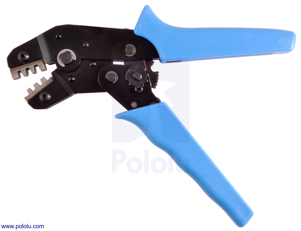 |
Crimping tool: 0.1-1.0 mm² capacity, 16-28 AWG. |
|---|
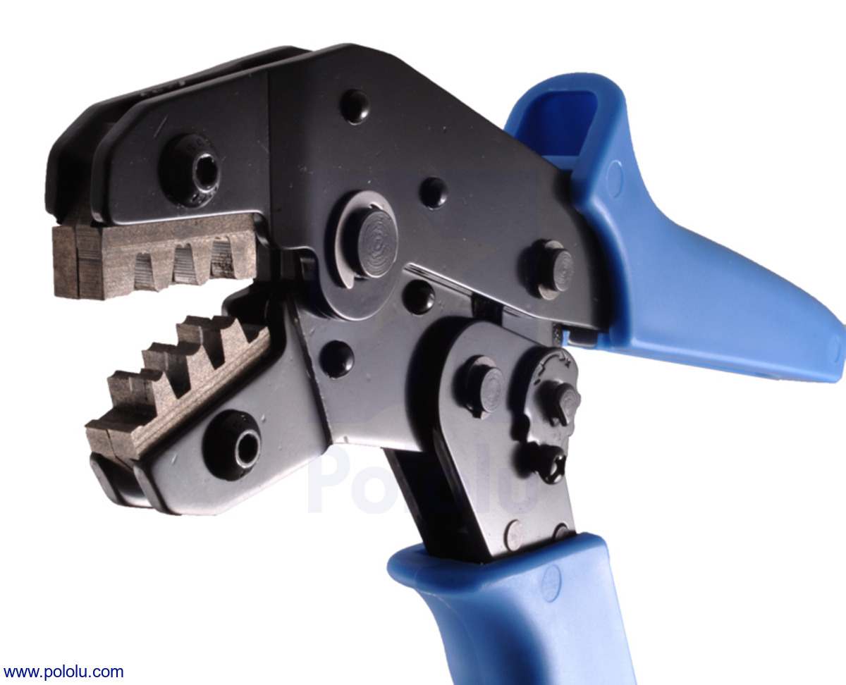 |
Crimping tool: 0.1-1.0 mm² capacity, 16-28 AWG. |
|---|
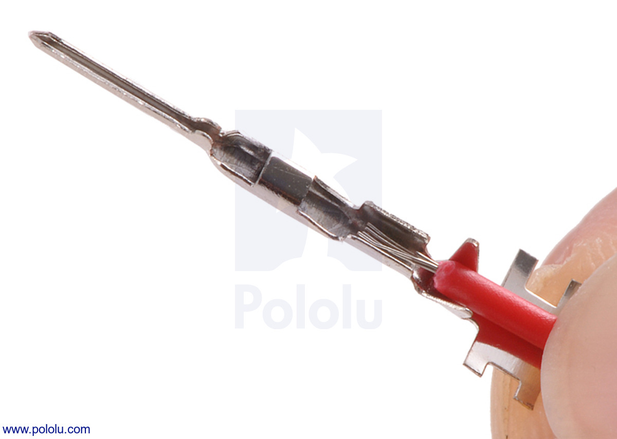 |
Preparing a wire and crimp pin. |
|---|
 |
Aligning the crimp pin in the tool. |
|---|
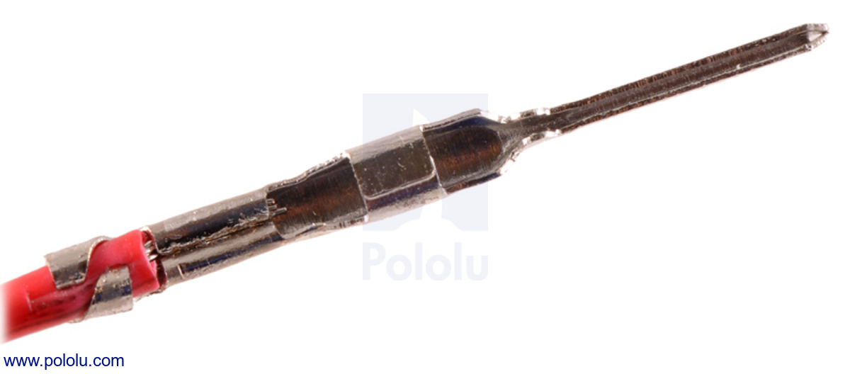 |
Correctly crimped 0.1" housing crimp pin using the wider (0.1-1.0 mm²) crimping tool (product #1928). |
|---|
|
|
We also have a less expensive, narrower (4 mm) crimper that can also crimp JST RCY, JR, Futaba J, and 0.1" housing crimp pins, though this alternate tool can only crimp the full extent of wire barrel on the JST RCY pins. You can use the following table to help you decide which cavity of which crimping tool you need:
| Tool | Cavity | Crimp Pins | Wire Gauge (AWG) |
|---|---|---|---|
| Crimping Tool: 0.1-1.0 mm² Capacity, 16-28 AWG | Outer | 0.1" Housing Female 0.1" Housing Male JST RCY Female JST RCY Male JR Female JR Male Futaba Female Futaba Male |
26-28 |
| Middle | 22-26 | ||
| Inner | Tamiya Female Tamiya Male Mini Tamiya Female Mini Tamiya Male |
16-20 | |
| Crimping Tool: 0.08-0.5 mm² Capacity, 20-28 AWG | Outer | 0.1" Housing Female 0.1" Housing Male JST RCY Female JST RCY Male JR Female JR Male Futaba Female Futaba Male |
26-28 |
| Inner | 22-26 |
Note: The manufacturer of the Crimping Tool: 0.1-1.0 mm² Capacity, 16-28 AWG has started including a label indicating 18 AWG is the maximum intended wire size, but we have specifically confirmed that the tool can crimp our Tamiya and Mini Tamiya crimp pins onto 16 AWG wires.
Prepare the wire by stripping about 1/8" (3 mm) of insulation from the end. Place the wire in the crimp pin, lining it up so that the stripped portion lies between the inner set of tabs on the crimp pin, while insulated wire lies between the outer set of tabs.
Tip: Instead of removing the crimp pin from the reel by breaking it off at the base (as intended), it can be helpful to leave a small tab on the back of the crimp pin to help you line it up and hold it in place while crimping, as shown in the pictures below. Then, you can remove the tab after it is crimped.
|
Place the wire and crimp pin on the appropriate tooth of the tool’s die, making sure that the insulated end is on the raised and wider half of the tooth. The tabs should point toward the cavity on the other side of the die so that the tool bends them inward around the wire when it closes.
|
Close the jaws of the tool slowly and completely until they release. The tabs on a properly crimped pin should form one barrel around the wire conductors and another barrel for strain relief around the wire insulation.
|
Tip: The strain relief barrel sometimes ends up a little overly flattened, making it too wide to fit comfortably into the crimp pin housing. In such situations, you can use a pair of pliers to gently squeeze the wider axis of the barrel into a more cylindrical shape that will slide easily into the housing.
One of our customers has made a very nice video tutorial that talks about how to make custom cables with our pre-crimped wires and with self-crimped wires. The section on using our crimping tool starts at approximately 4:15 and shows the process in detail. One of our distributors has also made a short video tutorial that shows how to use this crimping tool.
This useful inspection chart (pdf) by JST shows properties of good and bad crimp connections to look out for when checking your own connections.
This useful inspection chart by JST shows properties of good and bad crimp connections to look out for.
This video, created by customer Derek Molloy, discusses various options for making custom cables with our crimp connector housings, such as by using our pre-crimped wires or crimping your own with our wider crimping tool, though the same technique works with our narrower crimping tool as well. The section on using the crimping tool starts at around 4:15.
This video, created by our distributor, Proto-PIC, shows how to use our wider crimping tool, though the same technique works with our narrower crimping tool as well.
No FAQs available.
No blog posts to show.