

This is a merged information page for Item #2299.
View normal product page.
Pololu item #:
2299
Brand:
Sanyo Denki

This pancake bipolar stepping motor from Sanyo has a 1.8° step angle (200 steps/revolution). It offers a holding torque of 2.2 kg-cm (30 oz-in), and each phase draws 1 A at 5.9 V. This stepper motor’s flat profile (21 mm including the shaft) allows it to be used in places where more traditional stepper motors would be too bulky.
 Compare all products in Stepper Motors.
|
Sanyo pancake stepper motor: bipolar, 200 steps/rev, 50×16mm, 4.5V, 1000mA (SS2502-5041/SS2502-8040). |
|---|
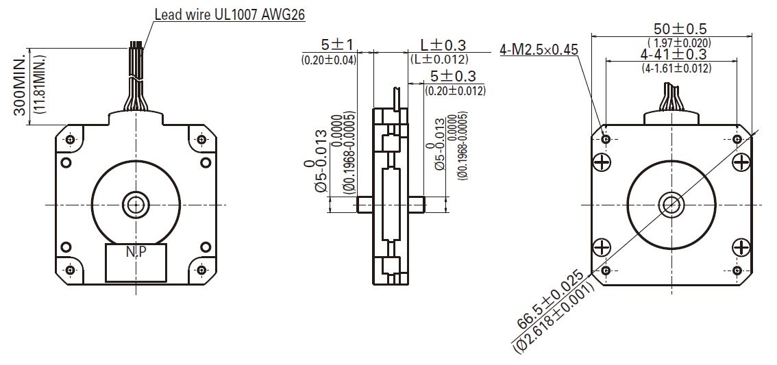 |
Dimensions (in mm) of the Sanyo 50×11mm pancake stepper motor. |
|---|
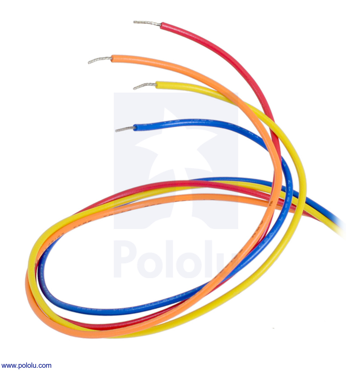 |
Bipolar stepper motor wires are terminated with bare leads. |
|---|
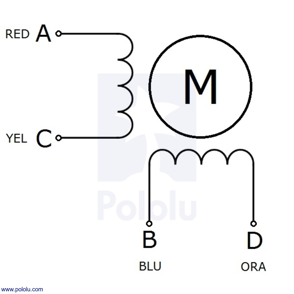 |
Sanyo bipolar stepper motor wiring diagram. |
|---|
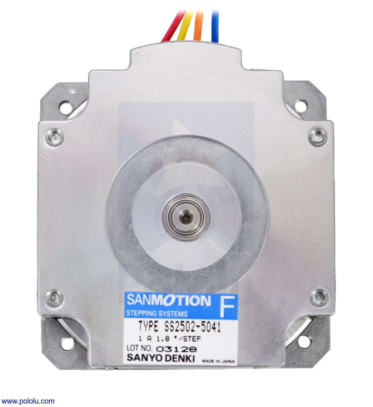 |
Bottom view of the 50×16mm Sanyo pancake stepper motor. |
|---|
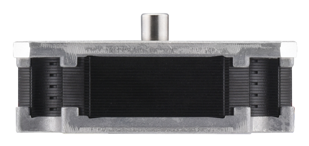 |
Side view of the 50×16mm Sanyo pancake stepper motor. |
|---|
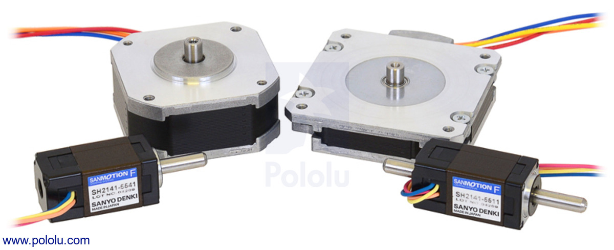 |
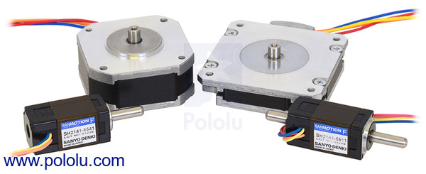
Sanyo stepper motors; from left to right: 14mm single shaft, 42×18.6mm, 50×11mm, 14mm double shaft |
|---|
|
Bipolar stepper motor wires are terminated with bare leads. |
|---|
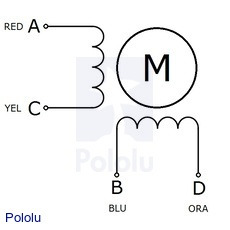 |
Sanyo bipolar stepper motor wiring diagram. |
|---|
This pancake bipolar stepping motor from Sanyo has a 1.8° step angle (200 steps/revolution). Each phase draws 1 A at 5.9 V, allowing for a holding torque of 2.2 kg-cm (30 oz-in). The motor has four color-coded wires terminated with bare leads: red and yellow connect to one coil; orange and blue connect to the other. It can be controlled by a pair of suitable H-bridges (one for each coil), but we recommend using a bipolar stepper motor driver or one of our Tic Stepper Motor Controllers. In particular, the Tics make control easy because they support six different interfaces (USB, TTL serial, I²C, RC, analog voltages, and quadrature encoder) and are configurable over USB with our free configuration utility.
Our 5 mm universal mounting hub can be used to mount objects on the stepper motor’s 5 mm-diameter output shaft.
More specifications are available in the datasheet (352k pdf).
|
Side view of the 50×16mm Sanyo pancake stepper motor. |
|---|
The following diagram shows the stepper motor dimensions in mm. The dimension labeled “L” is 16 mm. Though the dimension diagram below shows output shafts on both sides, this stepper motor only has a single output shaft (on the side with the mounting plate) with a length of 5 mm and a diameter of 5 mm. This shaft works with our 5 mm universal mounting hub.
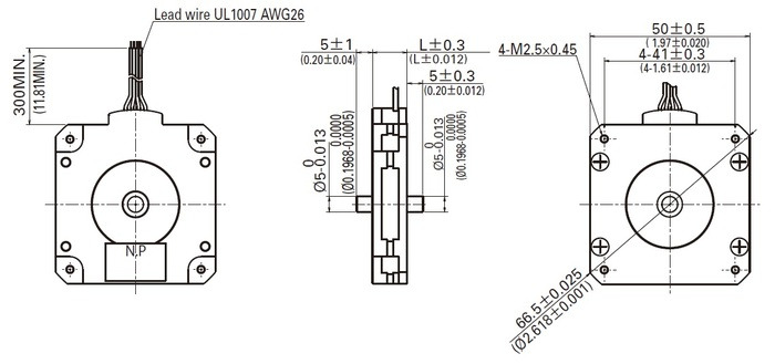 |
We also carry a thinner version of this stepper motor where “L” in the above diagram is 11 mm and all other dimensions are the same.
|
Bottom view of the 50×16mm Sanyo pancake stepper motor. |
|---|
Stepper motors are generally used in a variety of applications where precise position control is desirable and the cost or complexity of a feedback control system is unwarranted. Here are a few applications where stepper motors are often found:
 |
Sanyo stepper motors; from left to right: 14mm single shaft, 42×18.6mm, 50×11mm, 14mm double shaft |
|---|
Note: Sanyo Denki originally called this product the “SANMOTION F2 stepping motor model SS2502-5041”, but as of October 2014, they are transitioning to using the new part number SS2502-8040 or SS2502-8040P. This is only a part number change; the product itself is exactly the same.
| Size: | 50 mm square × 16 mm1 |
|---|---|
| Weight: | 150 g |
| Shaft diameter: | 5 mm |
| Current rating: | 1000 mA2 |
|---|---|
| Voltage rating: | 5.9 V |
| Model: | SS2502-5041, SS2502-8040, or SS2502-8040P |
| Holding torque: | 30.44 oz·in |
| Steps per revolution: | 200 |
| Resistance: | 5.9 Ohm2 |
| Inductance per phase: | 3.2 mH |
| Number of leads: | 4 |
| Lead length: | 30 cm |
| Encoders?: | N |
Yes. To avoid damaging your stepper motor, you want to avoid exceeding the rated current, which is 600 mA in this instance. All of our stepper motor drivers let you limit the maximum current, so as long as you set the limit below the rated current, you will be within spec for your motor, even if the voltage exceeds the rated voltage. The voltage rating is just the voltage at which each coil draws the rated current, so the coils of your stepper motor will draw 600 mA at 3.9 V. By using a higher voltage along with active current limiting, the current is able to ramp up faster, which lets you achieve higher step rates than you could using the rated voltage.
If you do want to use a lower motor supply voltage for other reasons, consider using our DRV8834 or STSPIN-220 low-voltage stepper motor drivers.
No blog posts to show.